4. Computer controlled cutting
This week I worked on defining my final project idea and started to getting used to the documentation process.
Group Assignment
For the group assignment, we characterized the laser cutter’s focus, power, speed, rate, kerf, and joint clearance. We tested different materials and settings to understand how the laser interacts with various materials and how to achieve optimal results for press-fit constructions.
You can find the detailed group work on our Group Assignment Page.
Individual Assignment
1. Concept & Design Philosophy
This assignment focuses on creating a parametric, press-fit construction kit. The design is based on a modular square unit with slots and bumps on all 4 sides. This simple, geometric form allows for high versatility, enabling the creation of extensive 2D grids, patterns, and by connecting squares at angles, complex 3D structures.
Core Component: A 25mm × 25mm square with 2 slots and 2 bumps on each side.
Key Feature: The universal slot design, which accounts for material thickness and laser kerf, ensures a perfect friction fit. Any slot can connect to any bump, allowing squares to be joined edge-to-edge to form larger assemblies.
2. Parametric Design in Fusion 360
I used Fusion 360 to create a parametric design that can be easily adjusted for different materials and laser cutters.
Parameters
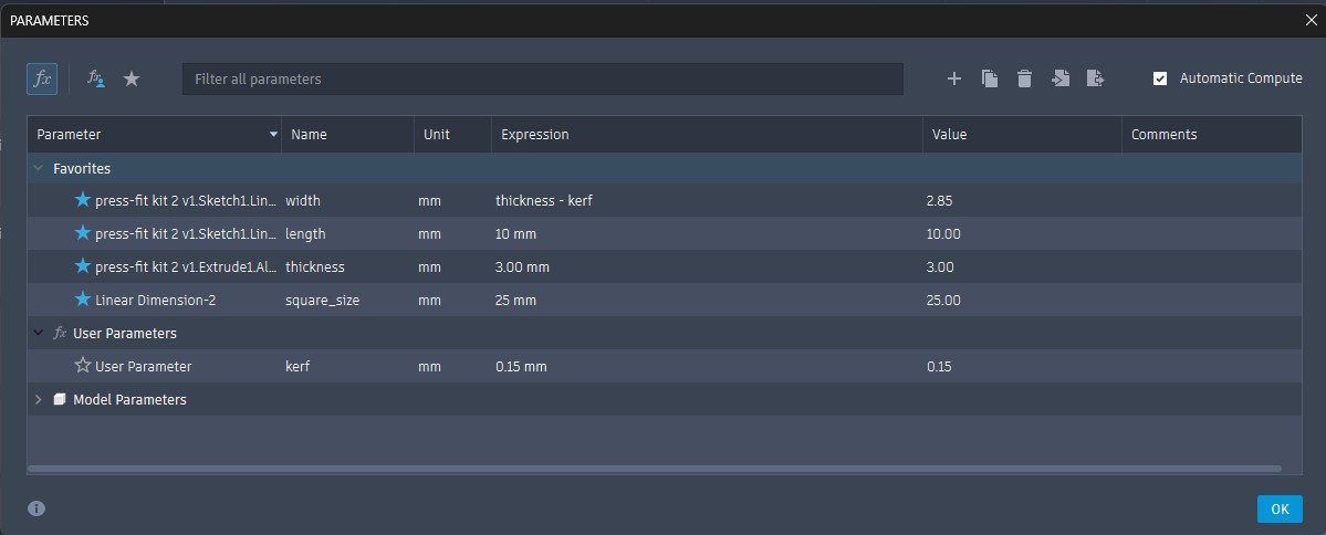
I defined the following parameters to make the design easily adjustable:
square_size= 25 mm (size of the square unit)thickness= 3 mm (thickness of the plywood)kerf= 0.15 mm (laser kerf determined through testing)width=thickness - kerf= 2.85 mm (width of the slots and bumps)length= 10 mm (length of the slots and bumps)
Design Steps
-
Create Base Sketch: I started by creating a sketch of a square with the dimension defined by the
square_sizeparameter. -
Add Slots and Bumps: Using the rectangle tool and constraints, I added slots and bumps on each side of the square. The dimensions were controlled by the parameters.
-
Apply Constraints: I used geometric constraints to ensure the slots and bumps were properly positioned and symmetrical.
-
Extrude: I extruded the sketch to create a 3D model with the thickness equal to
thickness.
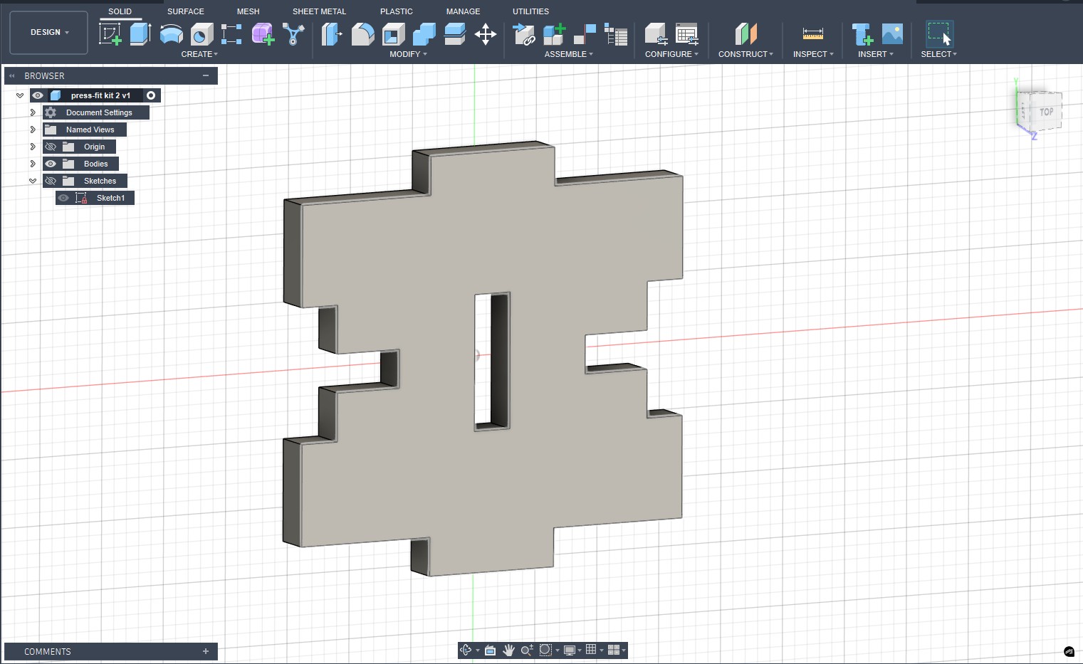 Final 3D model of the square unit
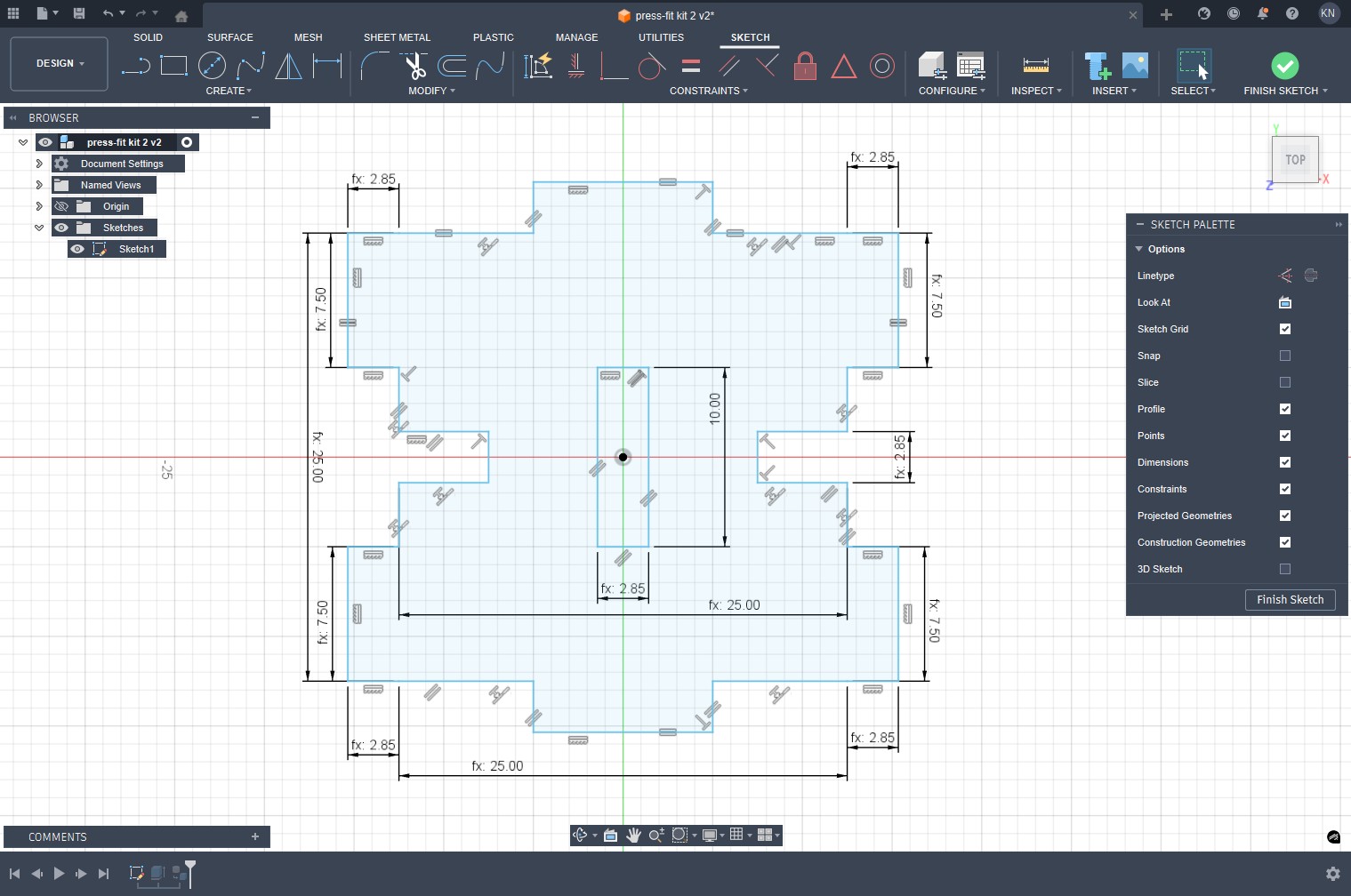 Parametric sketch showing constraints and dimensions
The Role of Kerf in the Design
Kerf is the width of material that the laser burns away during cutting. In press-fit designs, accounting for kerf is crucial because:
- If ignored, slots would be wider than intended, resulting in loose fits
- The actual slot width = designed slot width + kerf
- To compensate, we design slots narrower by the kerf amount:
width = thickness - kerf
This ensures that when cut, the actual slot width equals the material thickness, creating a perfect press-fit.
3. Laser Cutting Process
This section covers the physical fabrication process, from preparing the file for the laser cutter to assembling the final pieces.
From CAD to Laser Cutter
1.Exporting as DXF: I exported the sketch as a DXF file from Fusion 360.
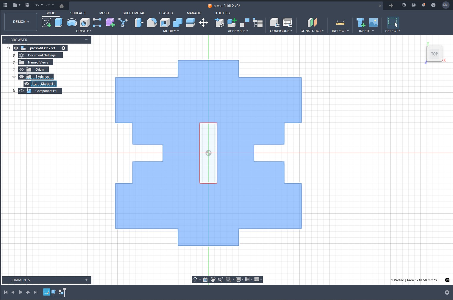 Sketch prepared for export as DXF
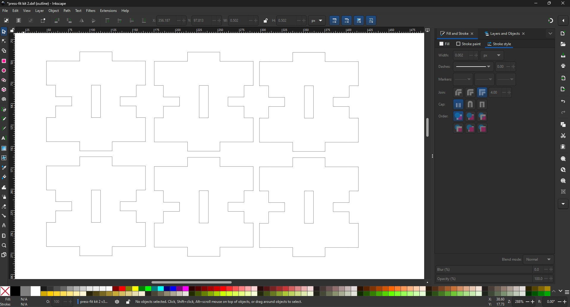
2.Prepare in Inkscape: Since the laser cutter software doesn’t directly accept DXF files, I opened the DXF in Inkscape and:
- Set the line width to 0.02 mm (hairline)
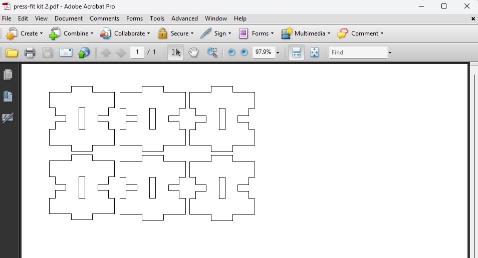
- Saved as PDF for printing
3.Laser Cutter Setup: I used the Epilog Fusion M2 40 laser cutter with 3mm plywood.
- Loaded the PDF file into the laser cutter software
- Set the origin to top-left corner
- Focused the laser using the manual focus tool
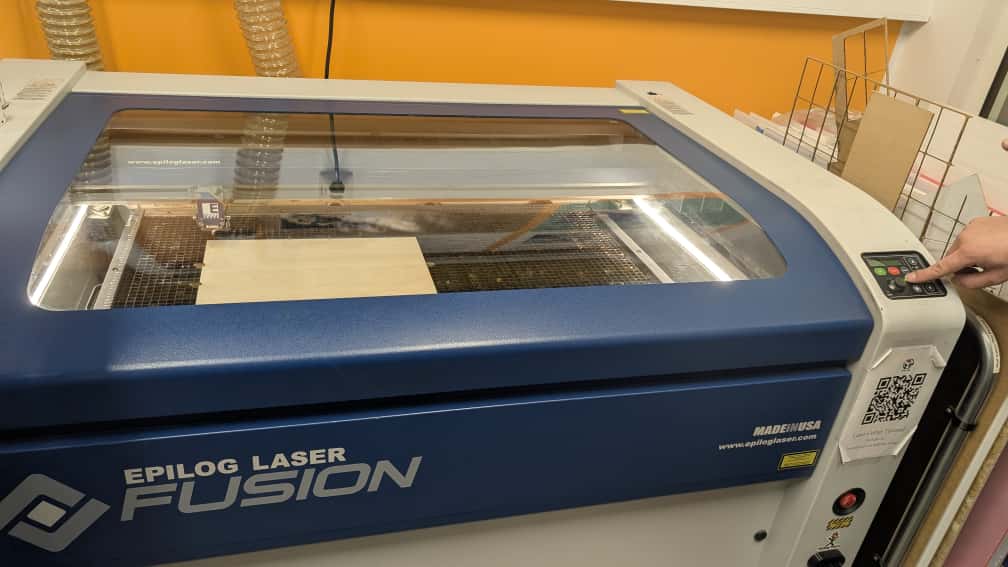 Setting the origin point
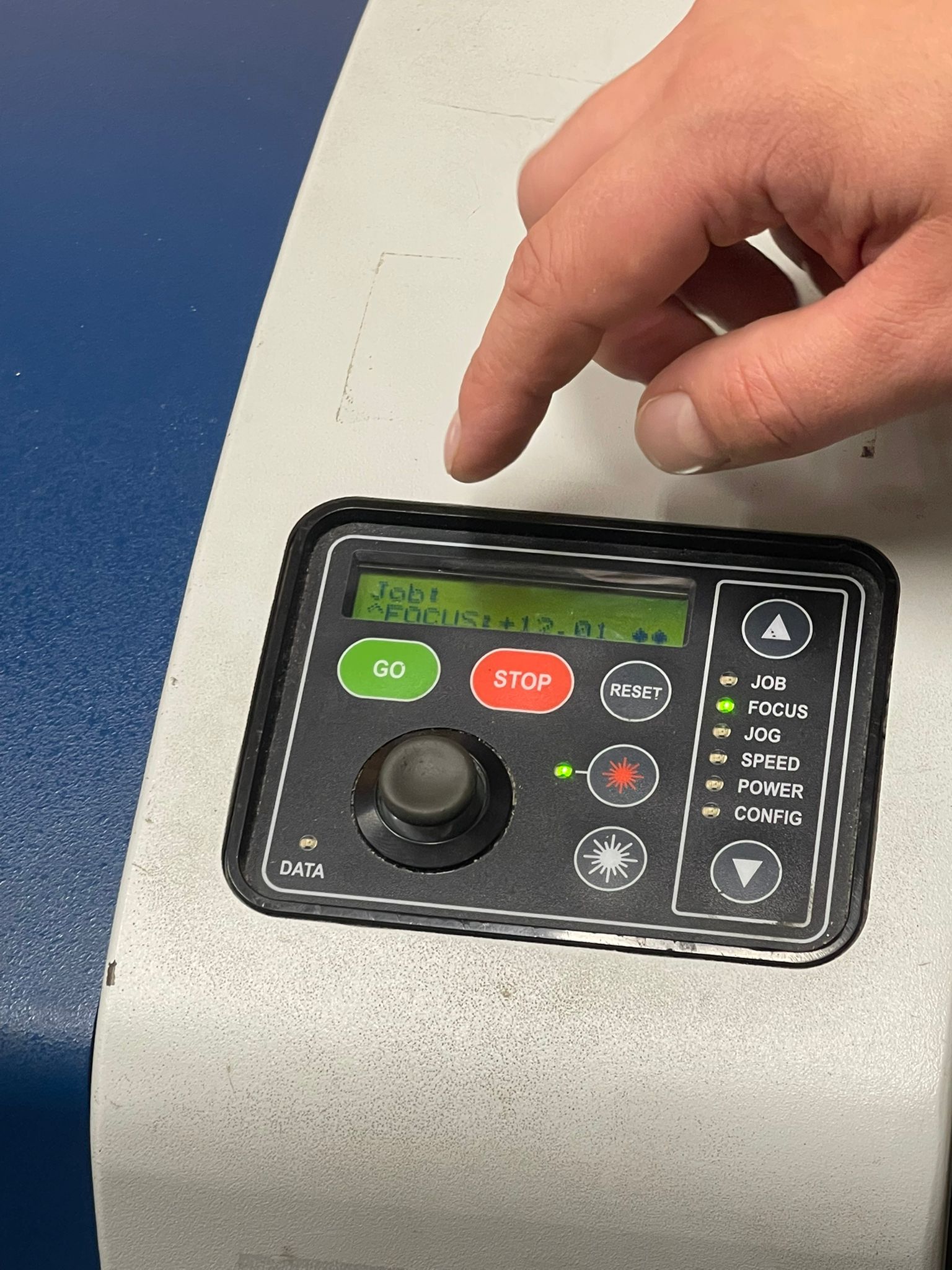 Focusing the laser
Kerf Testing and Calibration
Before cutting my final pieces, I conducted kerf tests to determine the exact kerf value for our specific material and laser settings.
1.Kerf Test Design: I created a comb test piece with fingers of varying widths (from 2.6mm to 3.2mm in 0.1mm increments).
2.Test Cutting: I cut the kerf test using the material (3mm plywood) and settings I planned to use for my final pieces:
- Speed: 65%
- Power: 100%
- Frequency: 50 Hz
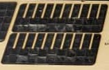
Cutting the kerf test piece
3.Finding Optimal Fit: I tested which finger fit snugly into its corresponding slot. The best fit was at 2.85mm, indicating a kerf of 0.15mm (since 3mm - 0.15mm = 2.85mm).
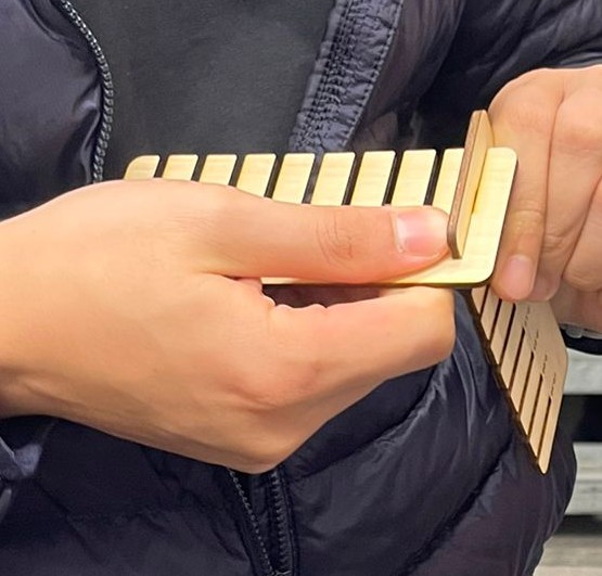
Kerf test piece after cutting
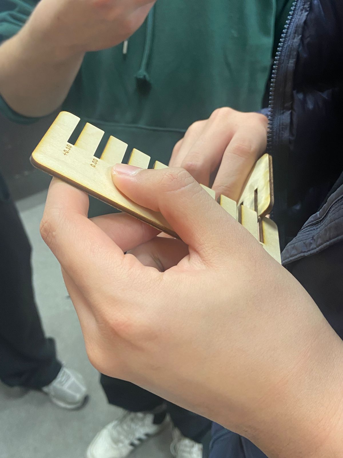 Testing the fit of different slot widths
Final Cutting - Material Selection Issue
For the final cutting of my pieces, I encountered a material inconsistency that taught me an important lesson about material awareness:
The Problem:
- I had conducted all my kerf testing and parameter development using 3mm plywood
- When preparing for the final cut, I accidentally used 3mm MDF instead of plywood without realizing the switch
- I proceeded with the same settings and parameters optimized for plywood
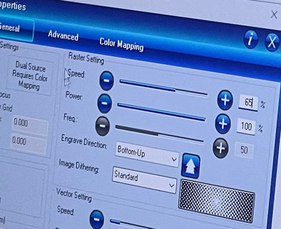 Laser cutter setting for final cutting
The Result:
- The MDF cut with significantly different characteristics than plywood
- The kerf compensation (0.15mm) that worked perfectly for plywood was incorrect for MDF
- The slots came out slightly too tight due to MDF’s different burning properties
- Assembly required more force than intended, and some pieces showed stress marks
Lessons Learned:
- Material Consistency is Critical: Always use the same material for testing and final production
- Different Materials, Different Kerf: MDF and plywood have different densities and resin content, affecting how they interact with the laser
- Visual Verification: Always double-check material type before cutting, as MDF and plywood can look similar but behave differently
- Test with Final Material: Kerf values should be determined specifically for each material type
Despite this oversight, the pieces were still functional and demonstrated the press-fit concept effectively, though with a tighter fit than optimal.
Assembly and Results
The press-fit construction kit assembled with satisfactory results:
1.2D Structures: I created flat grids and patterns by connecting squares edge-to-edge. The fit was tighter than ideal but held securely.
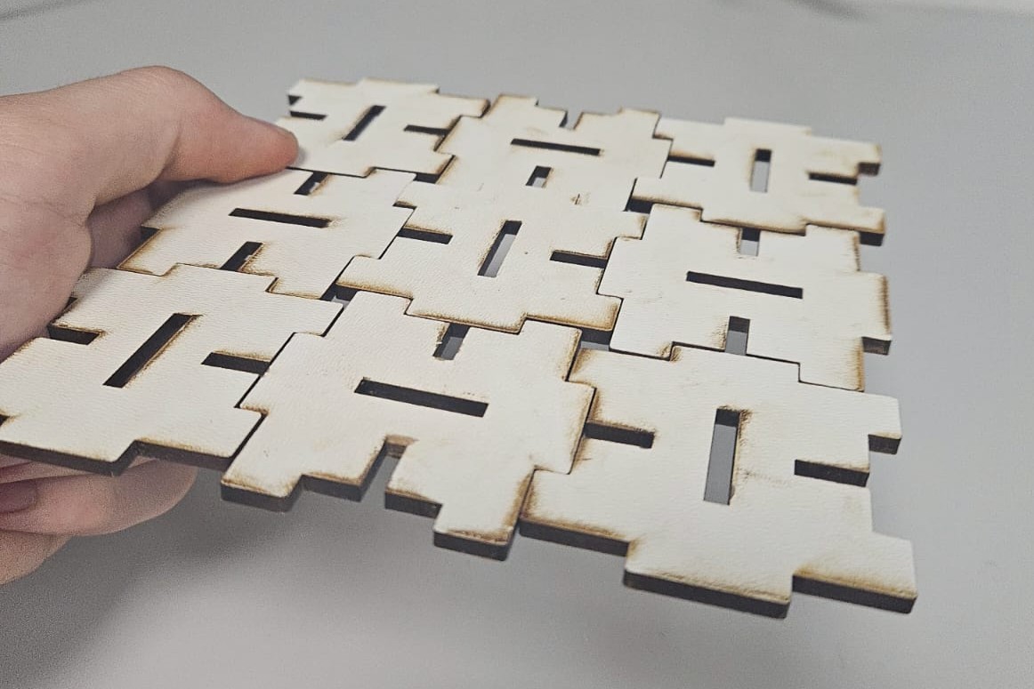 Flat grid assembly
2.3D Structures: By connecting squares at 90-degree angles, I formed cubes and more complex 3D structures. The tight fit actually provided excellent structural stability for 3D forms.
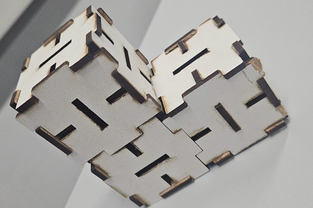 3D cube structure
The parametric design approach proved invaluable, and despite the material mix-up, the fundamental concept worked well. The experience highlighted the importance of material consistency in digital fabrication.
4. Vinyl Cutting
What I Made
I made a wolf vinyl sticker using the Cricut vinyl cutter. I chose this design because it looked cool and had a lot of details — perfect for testing how precise the machine can cut.
Step 1: Finding and Preparing the Design
I found a wolf design online. Here is the link: Ethnic Decorative Wolf on Freepik
What I did in Inkscape:
- Opened the downloaded file
- Scaled it to the size I wanted
- Made sure only the outlines remained (no fill color)
- Saved it as an SVG file
Why SVG? Cricut Design Space only accepts SVG for clean cut lines.
The original design: 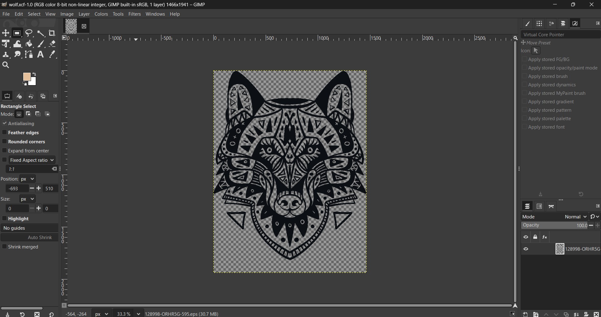
After removing fill, ready to cut: 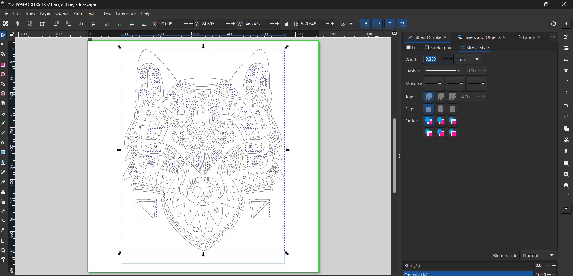
Step 2: Using Cricut Design Space
I opened Cricut Design Space and created a blank canvas.
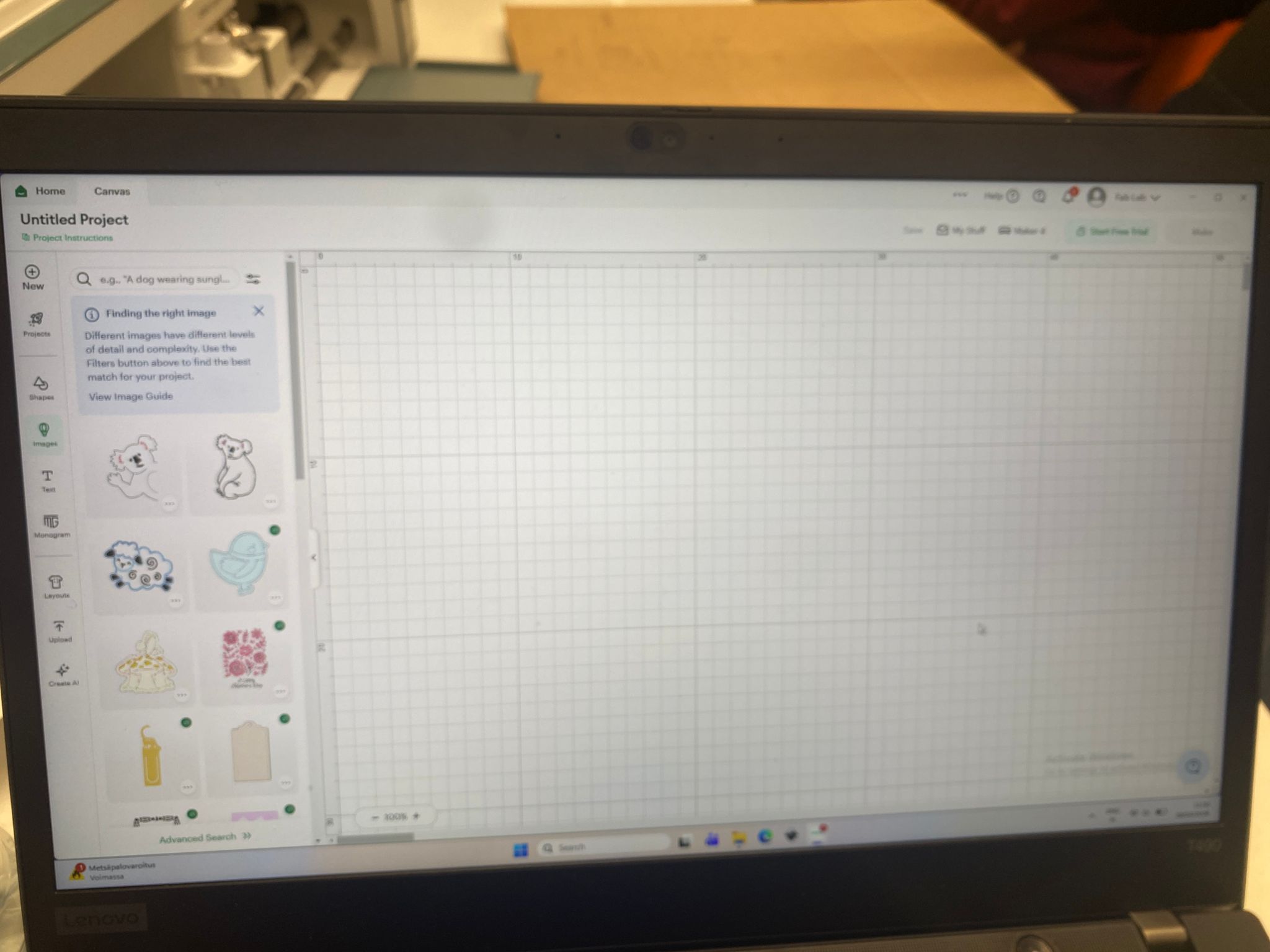
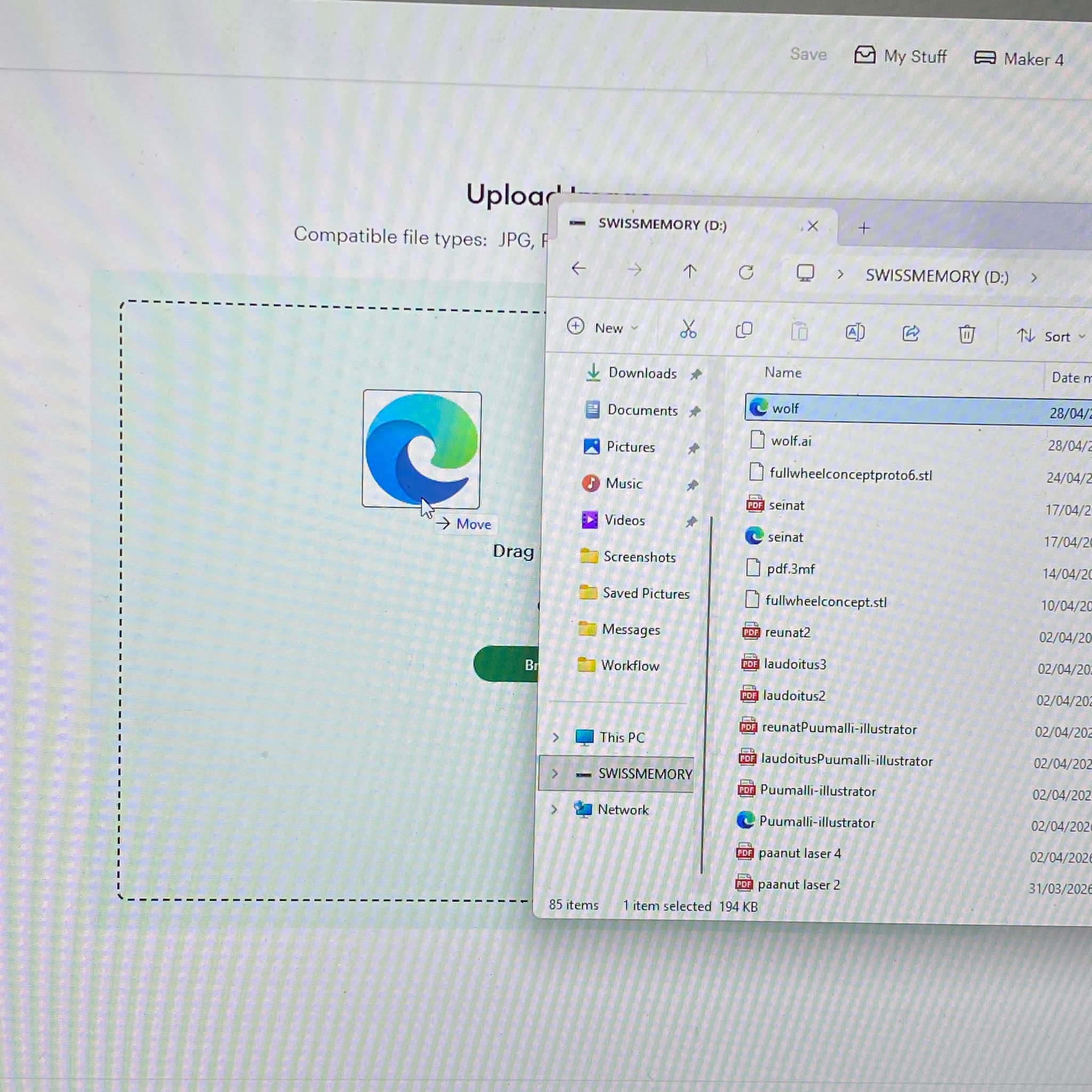
Uploading my file:
I clicked Upload, chose my SVG file, and imported it.
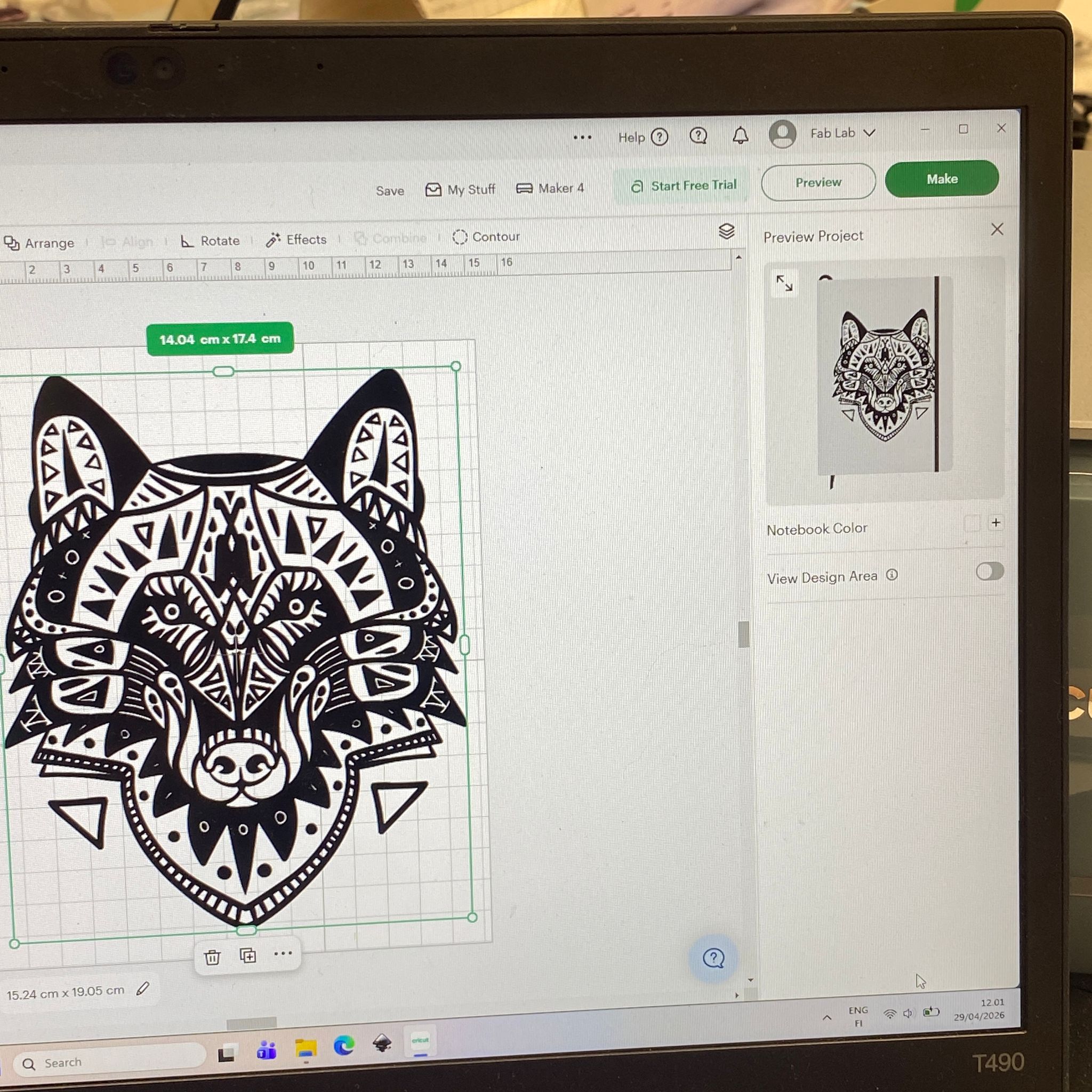
After upload:
The design appeared on my canvas.
Positioning on the mat:
I clicked the Make button. The software placed my design on a virtual cutting mat. I could move or rotate it to save vinyl.
Moving the design: 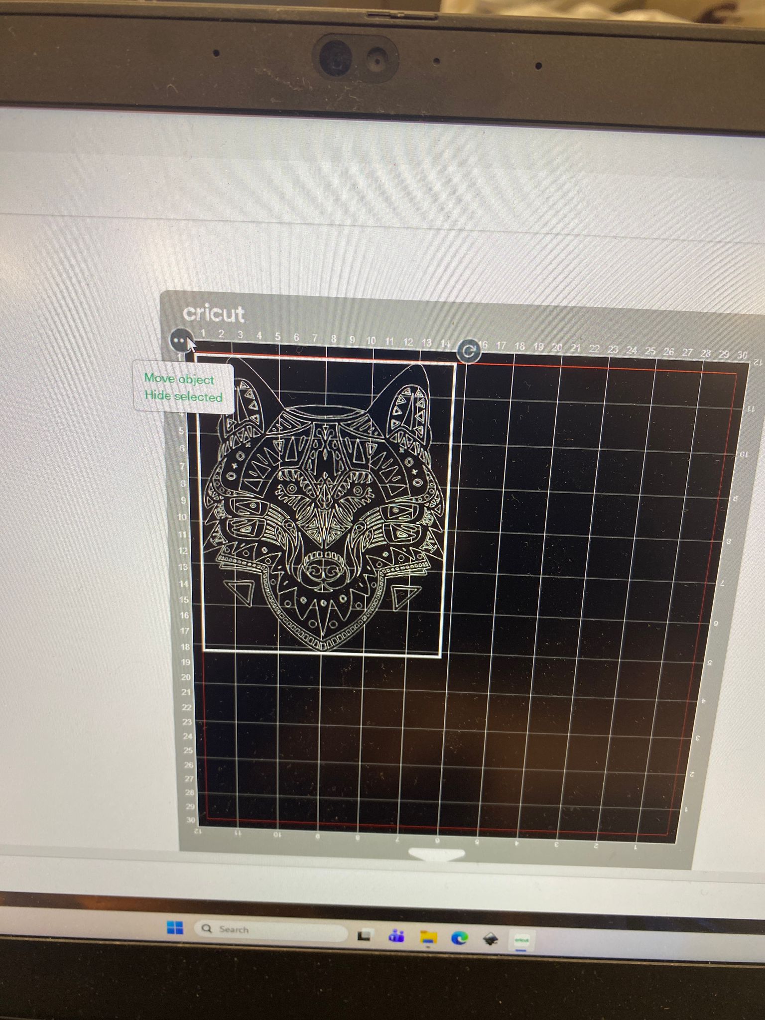
Rotating the design: 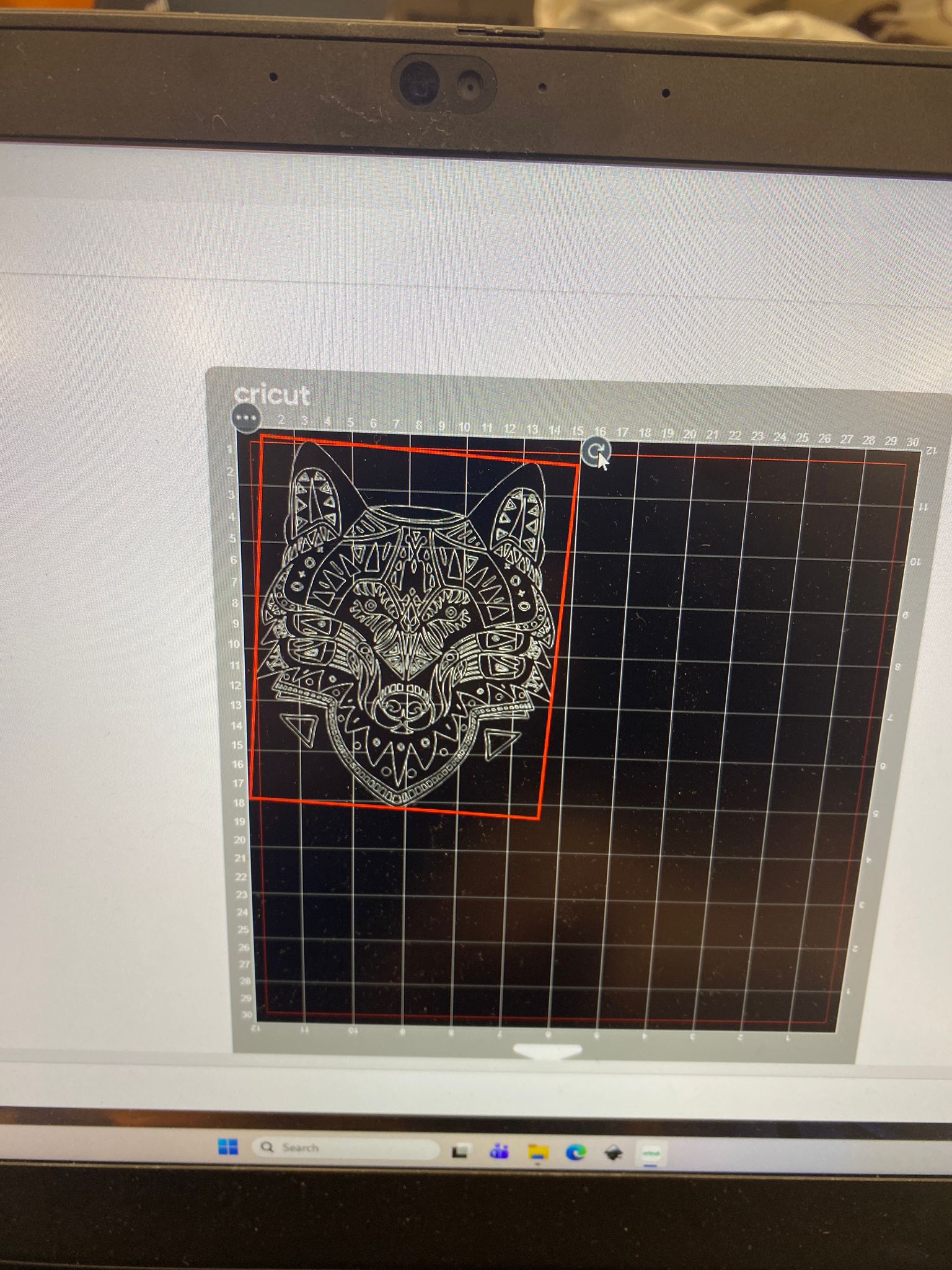
Step 3: Connecting to the Machine
I connected my computer to the Cricut Maker using USB.
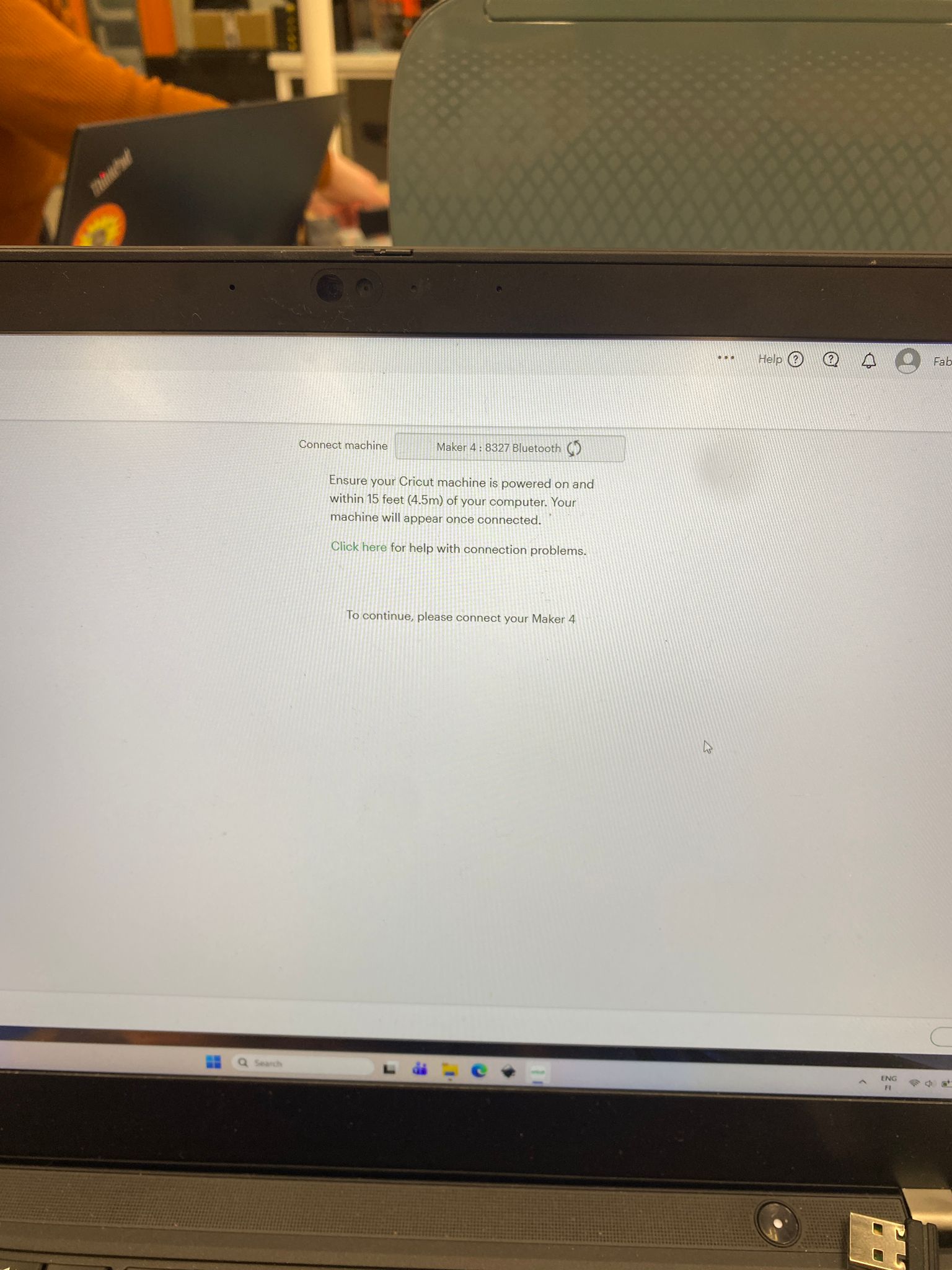
Step 4: Preparing the Machine and Material
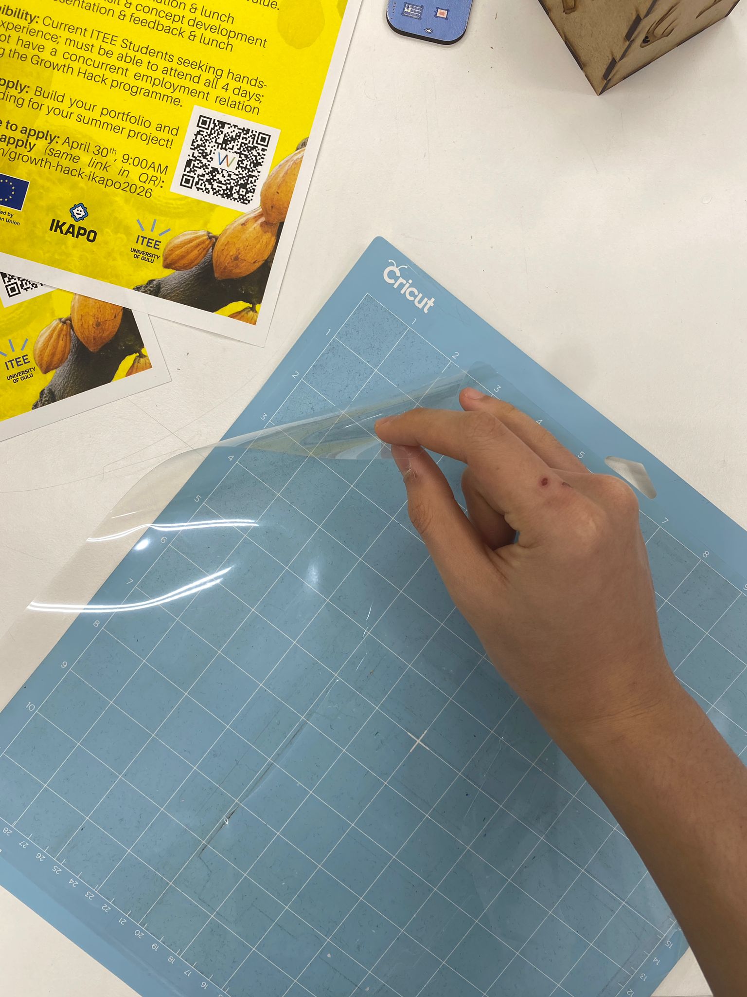
Removing the mat cover:
I peeled off the protective cover from the cutting mat.
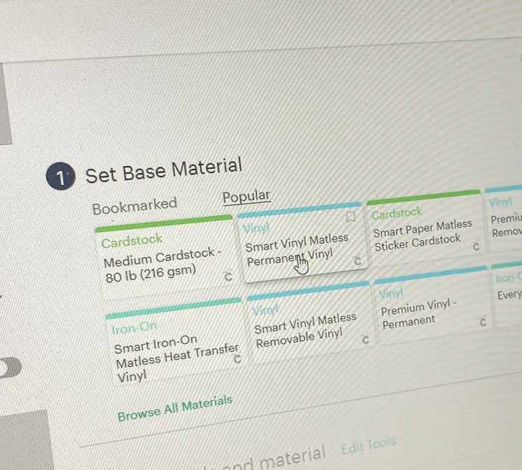
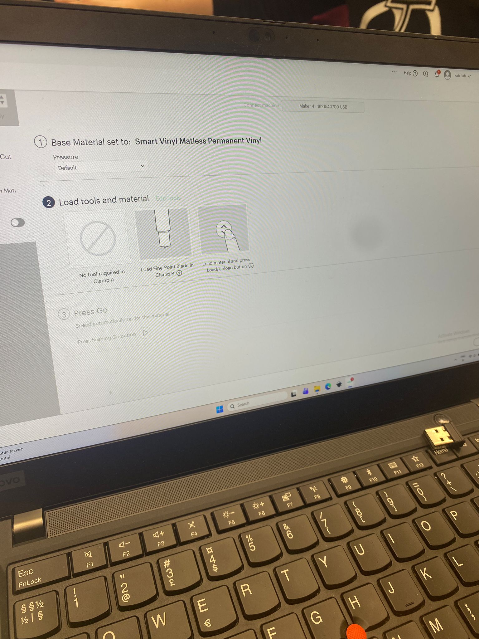
Choosing material type:
I selected “Vinyl” as the base material.
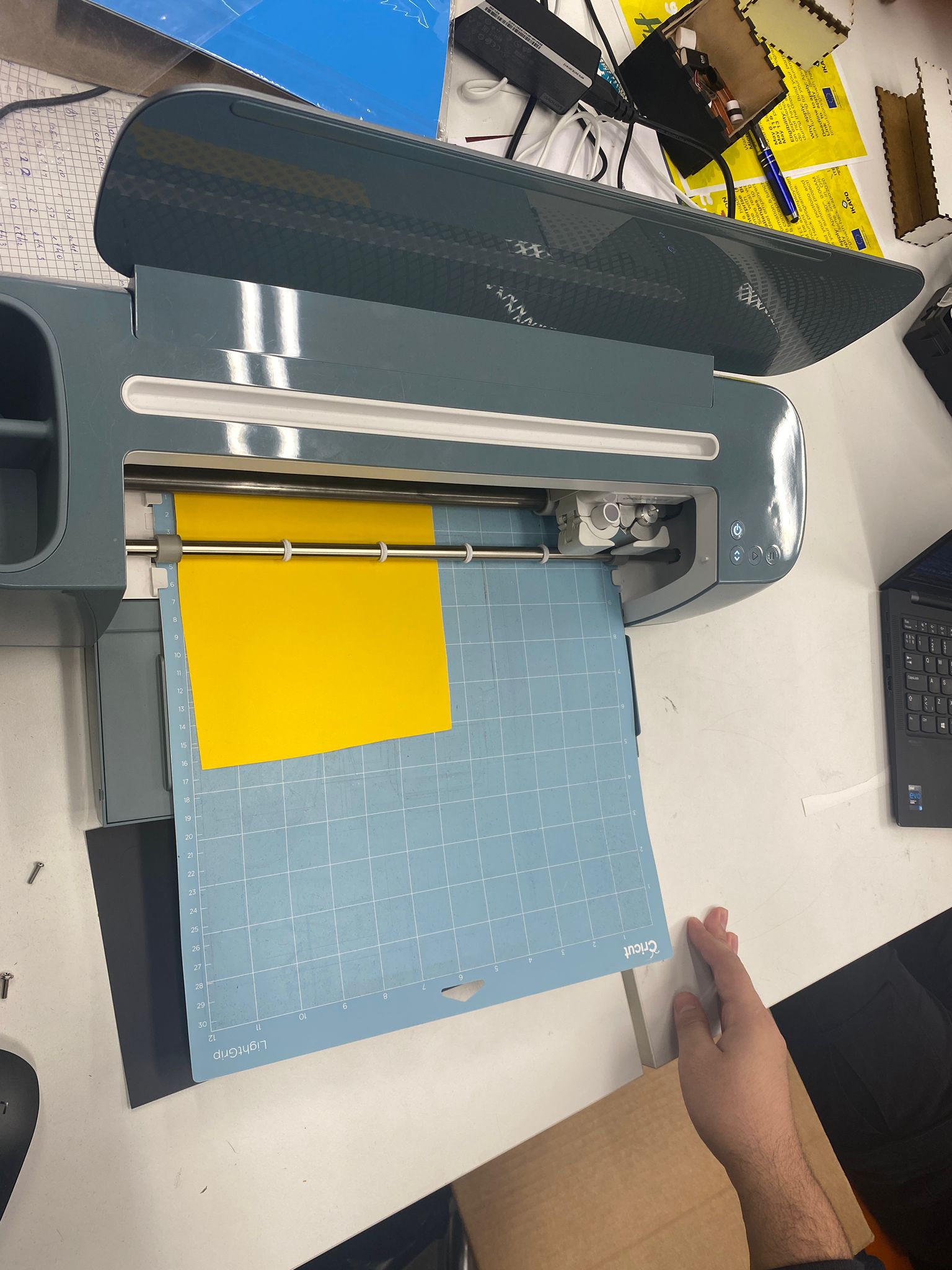
Loading the vinyl onto the mat:
I placed a yellow vinyl sheet onto the mat, aligning it with the corner.
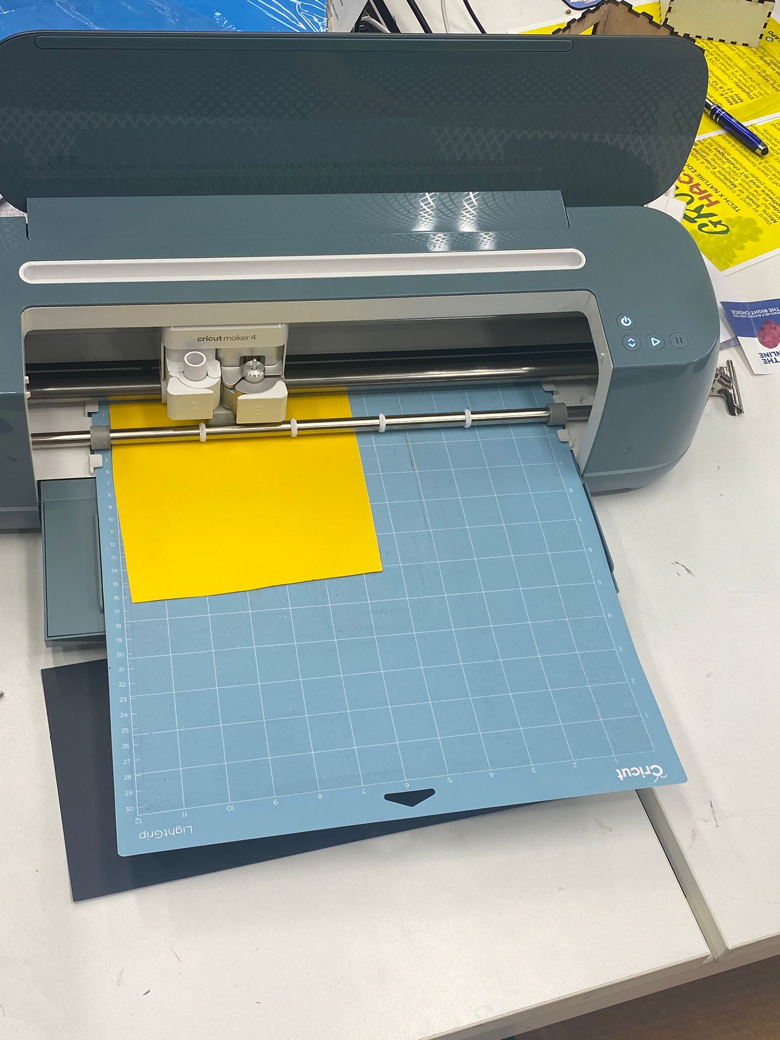
Vinyl on mat and Loading into machine:
Step 5: Cutting
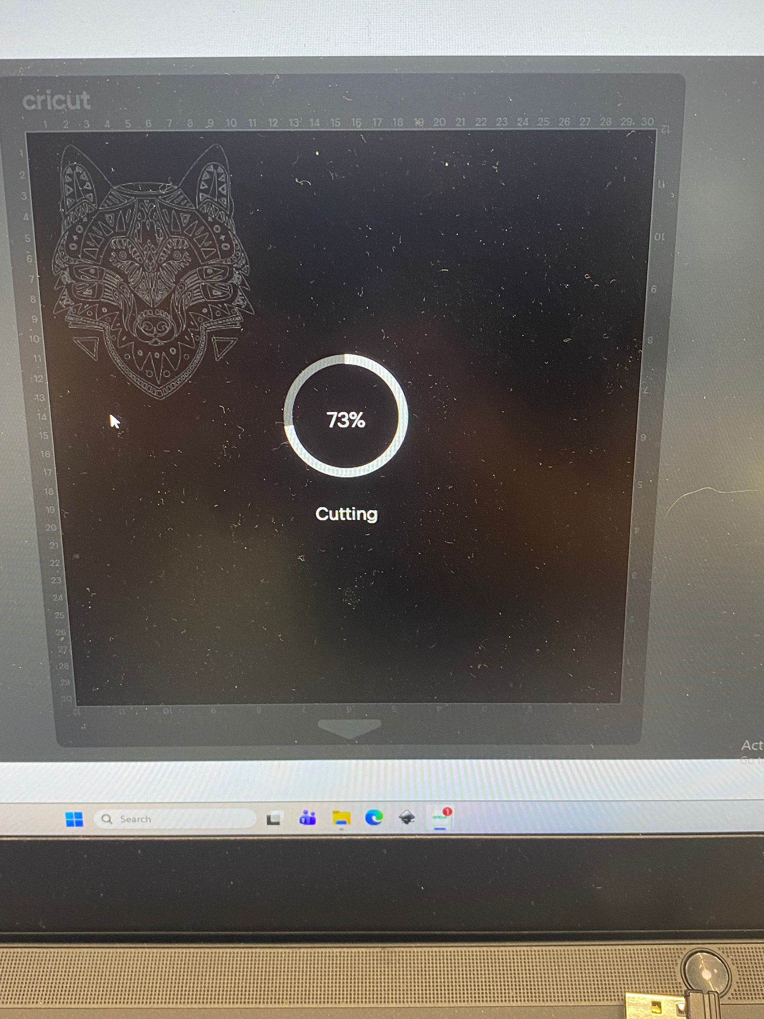
The machine started cutting along the lines.
Cutting in progress:
Step 6: Weeding (Removing Excess Vinyl)
After cutting finished, I removed the mat.
Right after cutting:
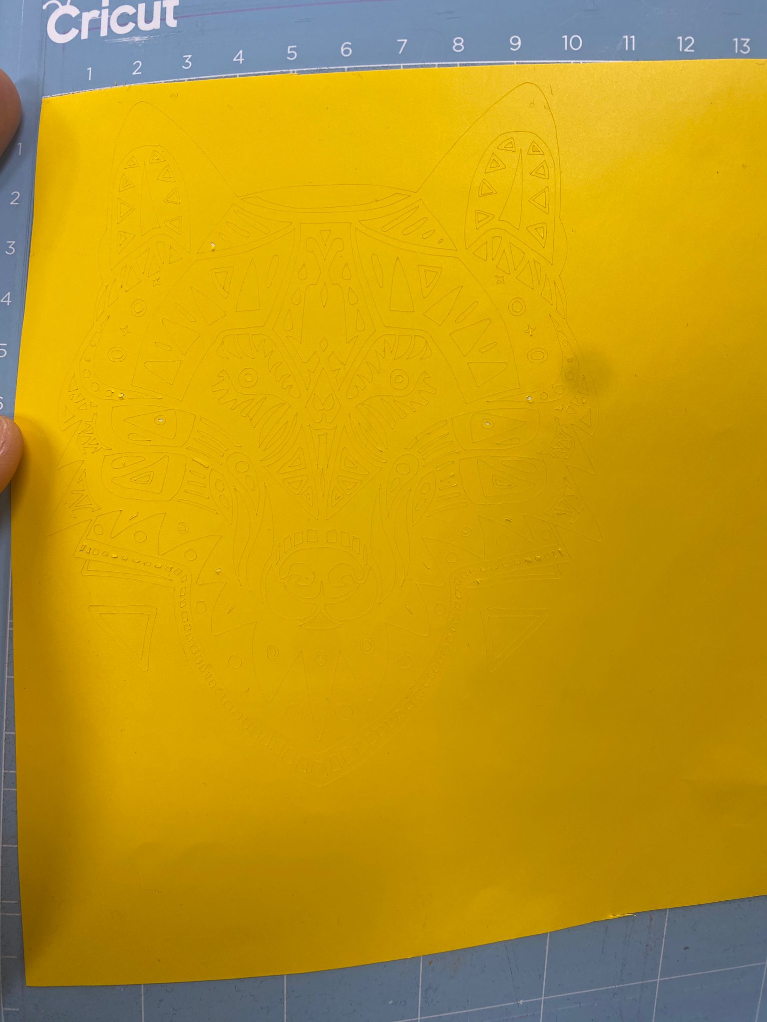
Weeding process:
I used a weeding tool to carefully remove the vinyl pieces that were not part of the design.
Weeding: 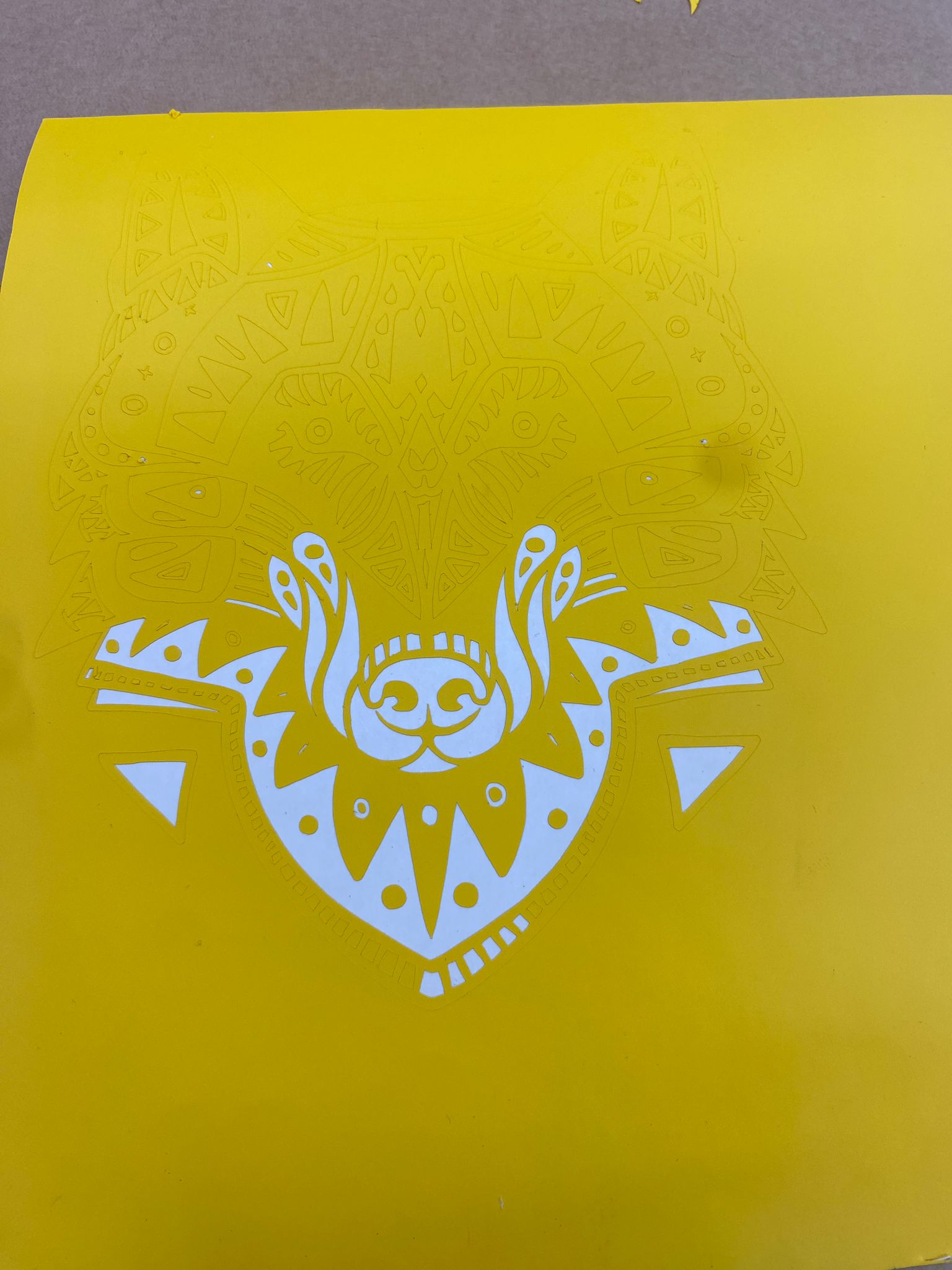
After weeding: 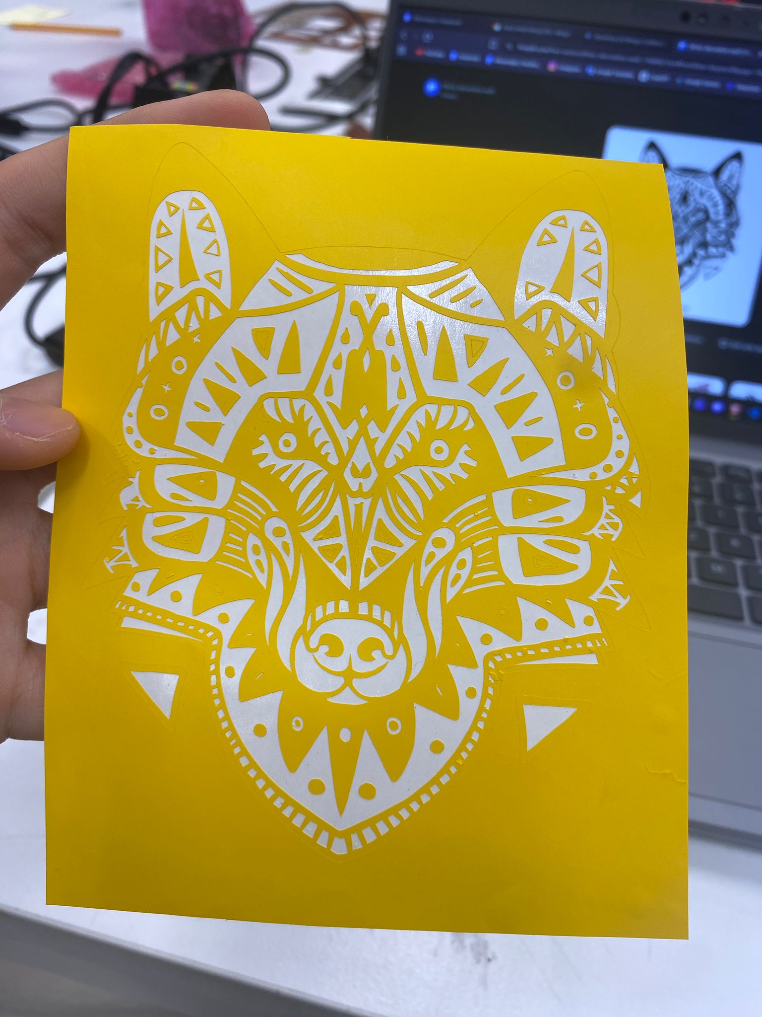
Note to myself: This design had many small pieces. Weeding took a long time. Next time, choose a simpler design.
Step 7: Applying Transfer Tape
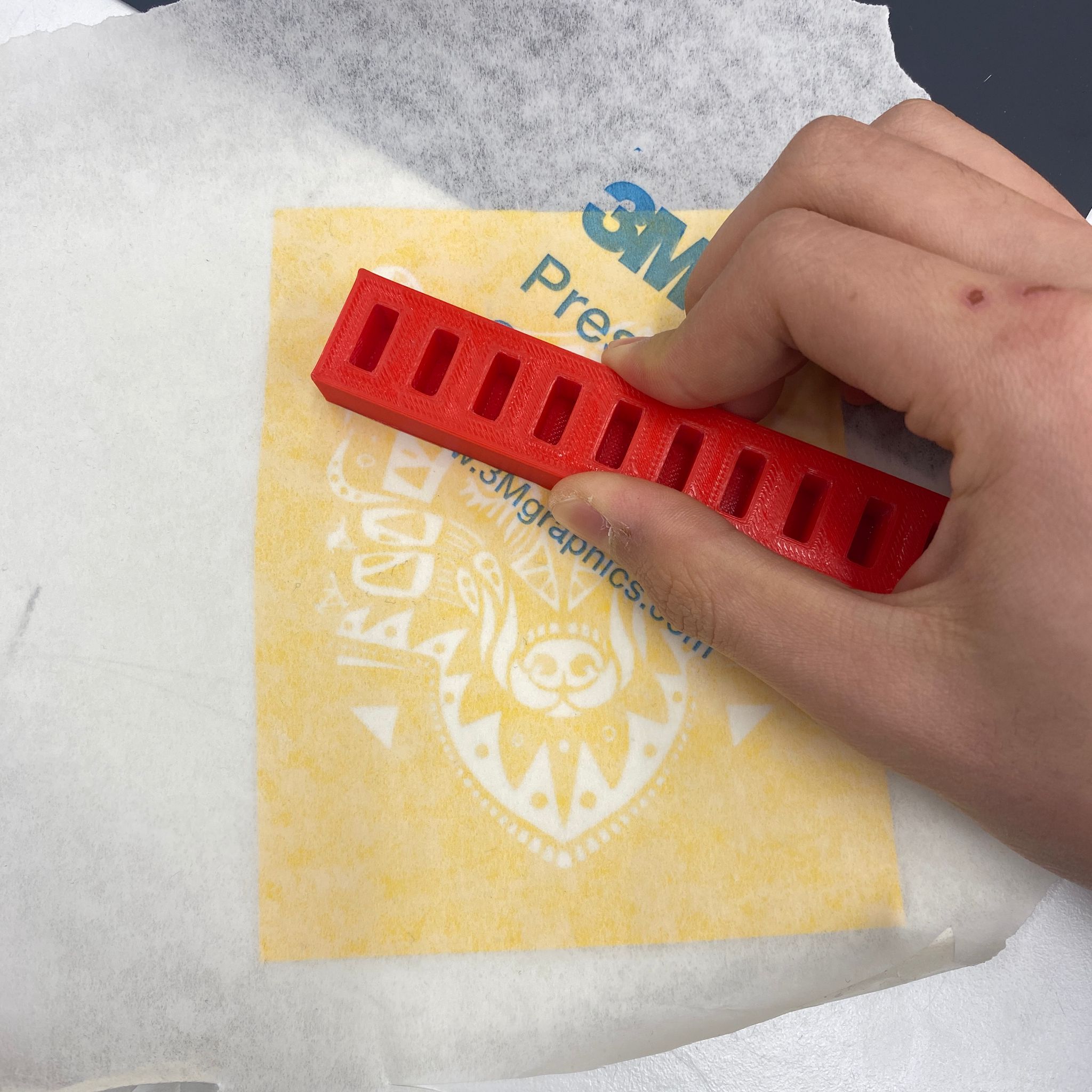
I placed transfer paper (sticky paper) over the weeded design.
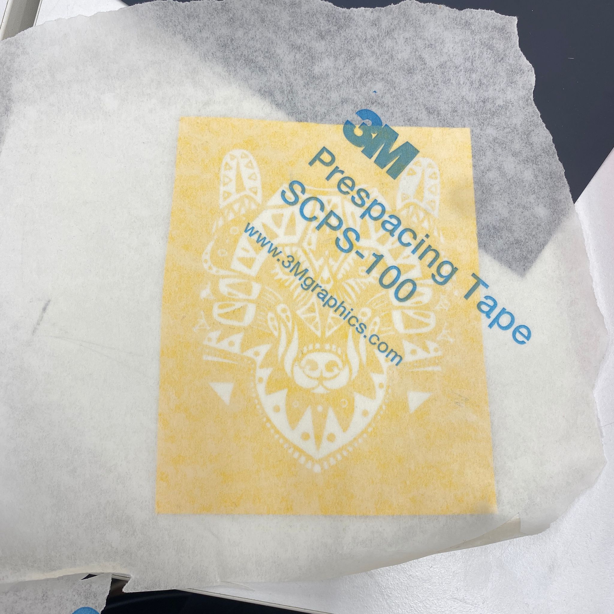
Pressing firmly:
I used a scraper tool to press the sticker hard onto the transfer paper. This helps all pieces stick.
Step 8: Removing the Backing
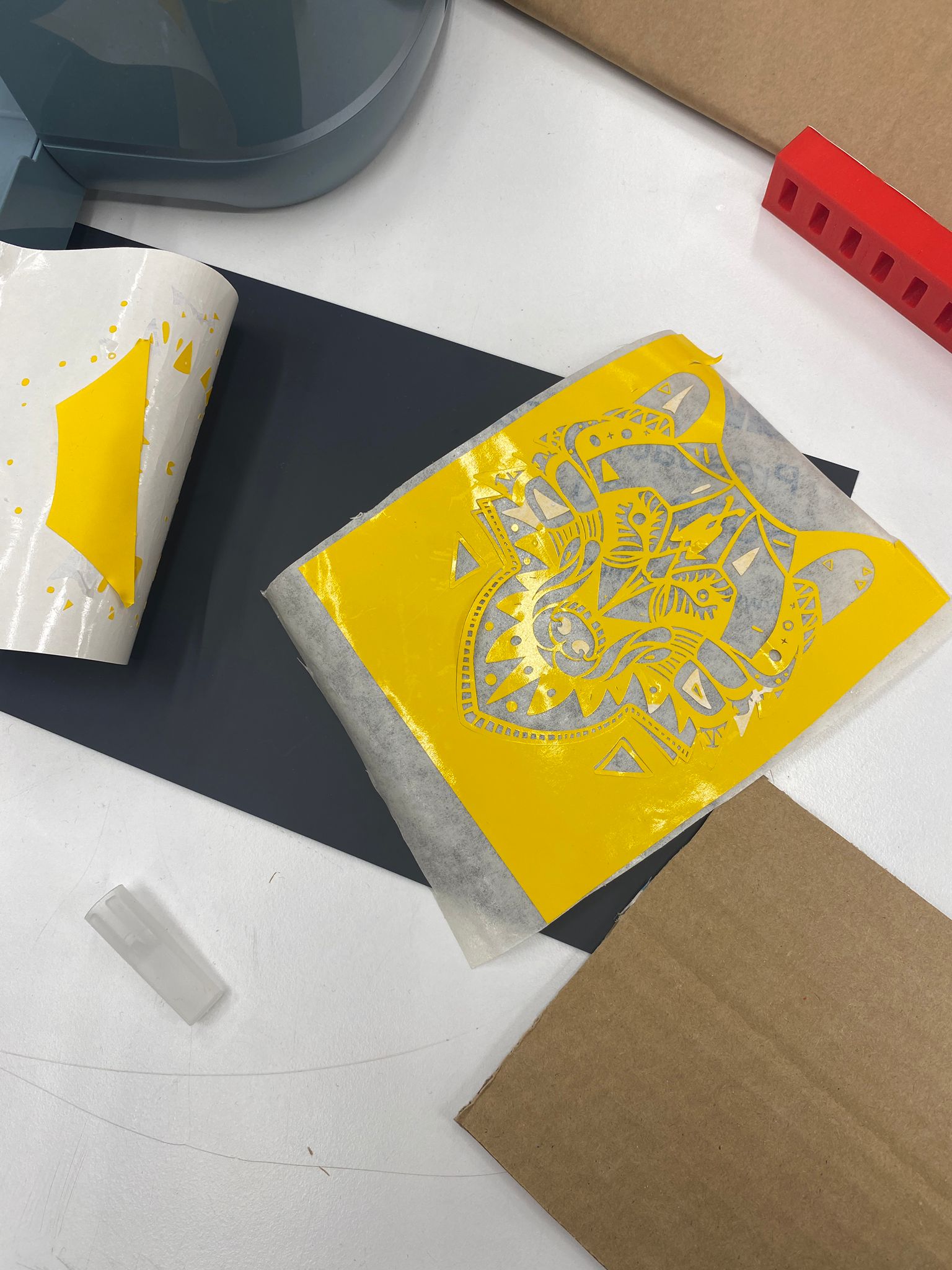
I peeled off the white backing paper. The vinyl stayed on the transfer tape.
Step 9: Applying to Surface
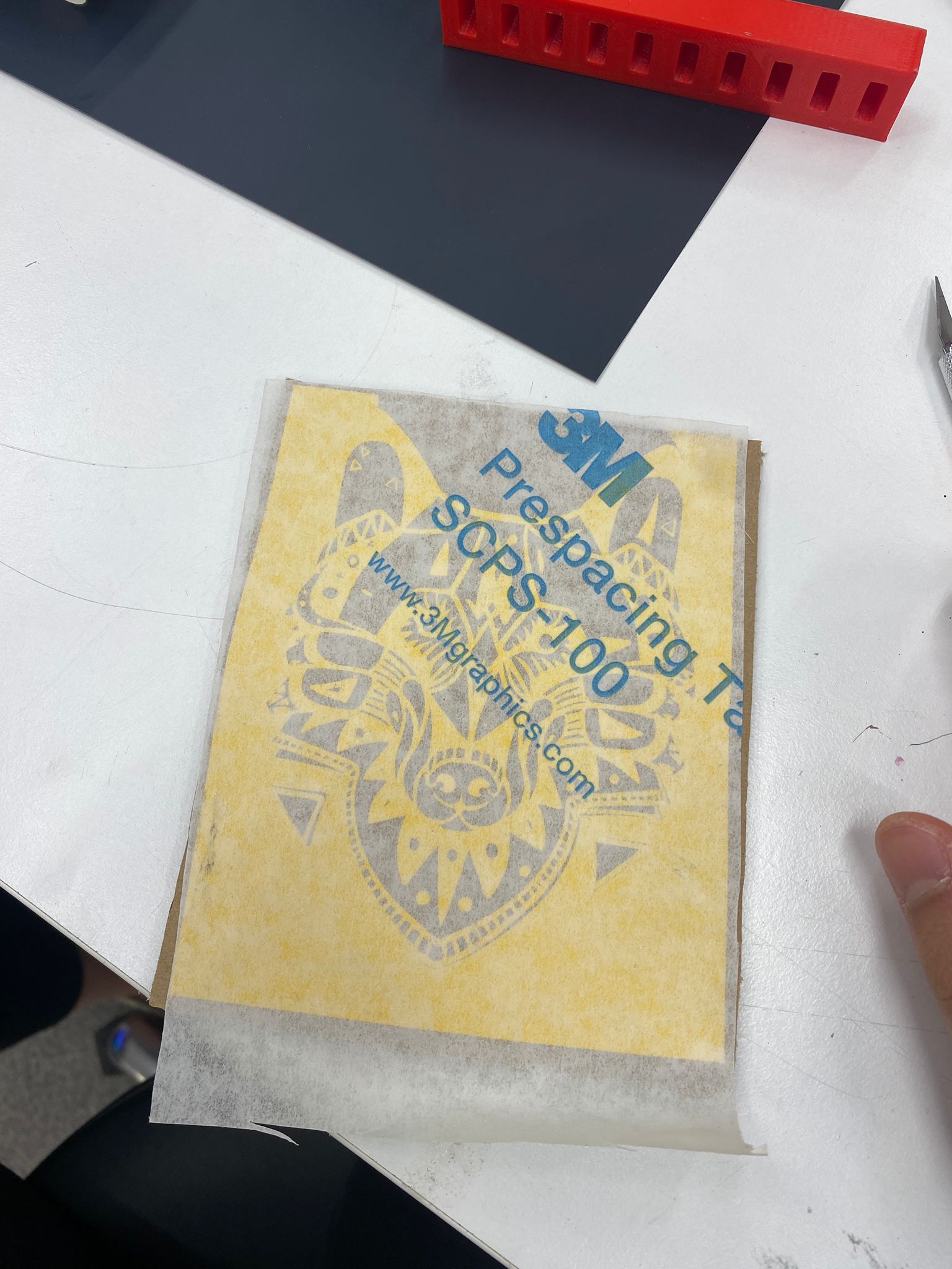
I placed the transfer tape onto a cardboard surface and pressed firmly.
Step 10: Removing Transfer Tape
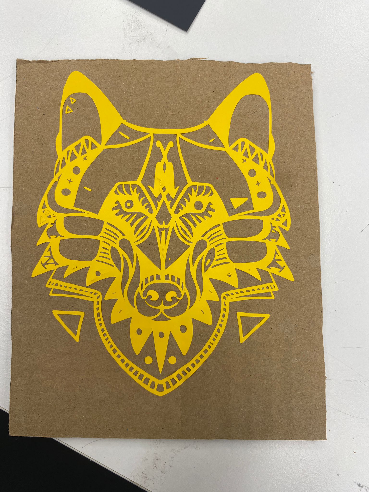
I carefully peeled off the transfer paper, leaving only the vinyl sticker.
What Went Wrong
| Problem | Why It Happened | How to Fix |
|---|---|---|
| Some small parts missing | Design was too complex with disconnected pieces | Choose a design where all vinyl parts connect together |
| Vinyl didn’t stick well to transfer paper | I left the vinyl exposed to air for too long. Dust collected on it. | Apply transfer paper immediately after weeding |
| Hard to weed | Too many tiny internal cuts | Start with a simpler sticker first |
Files


Conclusion
This week provided valuable hands-on experience with both laser cutting and vinyl cutting. The parametric design approach in Fusion 360, combined with proper kerf compensation, resulted in a successful press-fit construction kit. The vinyl cutting assignment demonstrated the precision possible with computer-controlled tools for decorative applications. Both processes highlighted the importance of understanding material properties, machine capabilities, and proper file preparation for successful digital fabrication.