9. Embedded programming
This week I worked on embedded programming for my seeed studio RP2040 to run with many codes.
Group Assignment: Toolchain & Workflow Comparison for Seeed XIAO RP2040
Objective: To demonstrate and compare three distinct development toolchains for the Seeed XIAO RP2040 microcontroller: MicroBlocks (visual, low-code), MicroPython (high-level text), and Arduino (C++).
Individual Assignment: Exploring the RP2040 & Peripheral Interaction
In my assignment, I have used AI to generate the structure base on the provided requirements for the assignment. However, the code and the descriptions for every parts are on my own writing.
How I Used AI for This Assignment
I used ChatGPT to help me with the following:
| Task | How AI Helped |
|---|---|
| I2C troubleshooting | Helped debug why hardware I2C wasn’t working |
| SoftI2C explanation | Provided clear explanation of difference between hardware and software I2C |
| Documentation organization | Suggested structure for comparing MicroPython vs Arduino |
My AI Prompts (Examples):
Prompt 1: “Why is my hardware I2C not working on XIAO RP2040? I am using pins D4 (SDA) and D5 (SCL).”
Prompt 2: “Explain the difference between SoftI2C and hardware I2C in MicroPython. Which one should I use?”
Prompt 3: “Convert this quaternion from BNO08x rotation vector to Roll, Pitch, Yaw angles in degrees. Write C++ code.”
Note: AI helped generate the structure and debug issues, but I personally tested, fixed, and verified all code on my actual hardware. The final code reflects my own understanding and debugging.
1. Browsing the Datasheet
For this assignment, I delved into the Raspberry Pi RP2040 Datasheet to understand the capabilities of the chip on my Seeed XIAO board.
Key Learnings from the RP2040 Datasheet:
The Microcontroller Board
I used the Seeed Studio XIAO RP2040 for this assignment.
- Official page: Seeed Studio XIAO RP2040
- Wiki documentation: wiki.seeedstudio.com/XIAO-RP2040
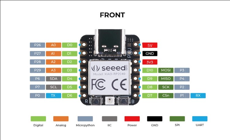
With the GPIO of the Seeed Studio XIAO RP2040. I search on wiki.seeedstudio.com.
The Sensor
I used the BNO085 9-axis absolute orientation sensor.
-
Datasheet link: BNO085 Datasheet (SparkFun)
-
I2C Communication: The RP2040 supports I2C protocol, which I used to communicate with the BNO08X sensor.
On MicroPython, I have to initialize devices on pins that are designed for MicroPython. On Arduino (C++), I used digital pins (green D) for calling pins
Pinout Confirmation:
I cross-referenced the Seeed XIAO schematic with the wiki Seeed Studio RP2040 web to confirm the following connections:
-
LED: GPIO 0 is routed to physical pin D6 on the XIAO board.
-
Button: GPIO 1 is routed to physical pin D7.
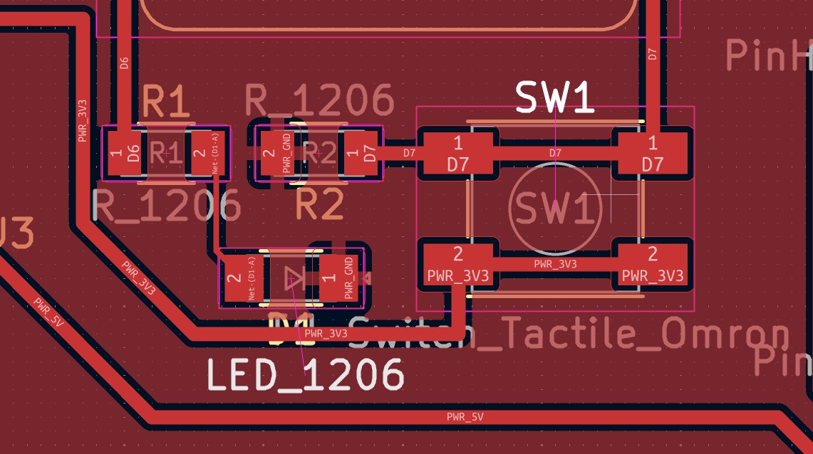
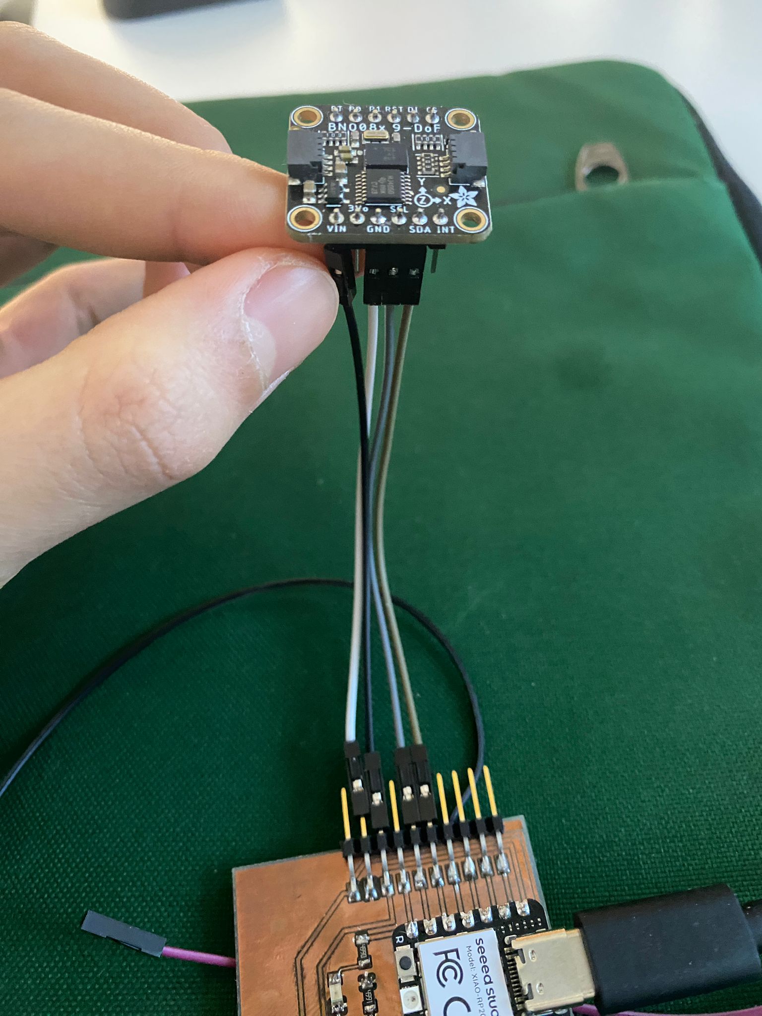
- BNO08X I2C:
- SDA → GPIO 6 (D4)
- SCL → GPIO 7 (D5)
- VCC → 3.3V
- GND → GND
- PS0 → GND (to select I2C mode)
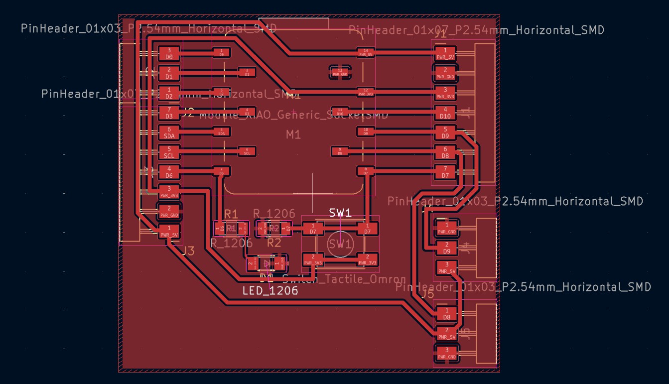
My PCB from Week 7
In this week, I used the board that I designed in the previous week. Link to the board design process
2. Program Design: Button-Triggered I2C Sensor Communication
Goal: To write a program that combines input, output, and wired communication. I decided to create a simple system using the I2C protocol to communicate with the BNO08x sensor and read its accelerometer data when a button is pressed.
Concept:
-
Input: The button on D7 acts as the trigger for sensor reading.
-
Communication: When the button is pressed, the XIAO RP2040 reads accelerometer data from the BNO08x sensor over the I2C bus.
-
Output:
-
The LED on D6 lights up when the button is pressed (visual feedback)
-
Accelerometer values (X, Y, Z) are printed to the Serial Monitor with ARDUINO, with MICROPYTHON show it receive data or not
-
The LED turns off when the button is released
Toolchain Selection:
For this task, I chose MicroPython with Thonny IDE. Since I was already familiar with Arduino (C++) from previous projects, I wanted to challenge myself by exploring a different development environment. MicroPython offered several advantages:
-
Interactive REPL: Allowed me to test I2C commands and sensor communication in real-time
-
Concise Syntax: The code is more readable and requires less boilerplate than Arduino
-
Rapid Prototyping: Changes can be tested immediately without lengthy compilation times
I also implemented the same functionality in Arduino (C++) for comparison, which I documented in a separate section.
3. Code Implementation
3.1 MicroBlocks
Just some funny test on it.
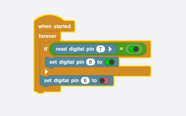
The result is that the LED is on when I press the button.
3.2 MicroPython Version (Thonny IDE)
Below is the code I used, also with description at each line
import machine
import time

# Hardware Setup
# Initialize I2C bus for BNO08x sensor
i2c = machine.SoftI2C(scl=machine.Pin(7), sda=machine.Pin(6), freq=100000)

# Initialize LED and Button
led = machine.Pin(0, machine.Pin.OUT)              # LED on D6 (GPIO0)
button = machine.Pin(1, machine.Pin.IN, machine.Pin.PULL_UP)  # Button on D7 (GPIO1)

# BNO08x I2C Address
BNO08X_I2C_ADDR = 0x4A

# State variables
last_button_state = 0  # Start with button not pressed
data_received = False

print("Ready - Press button to check sensor data")

while True:
    button_state = button.value()

    # Button pressed
    if button_state == 1:
        led.value(1)  # Turn LED ON

        # Check if this is a new button press
        if last_button_state == 0:
            print("Checking sensor...", end=" ")

            try:
                # Attempt to read data from BNO08x sensor
                data = i2c.readfrom(BNO08X_I2C_ADDR, 4)

                # If we get data, sensor is responding
                if data and len(data) > 0:
                    data_received = True
                    print("DATA RECEIVED!")
                    print(f"Raw data: {data}")
                else:
                    data_received = False
                    print("NO DATA")

            except Exception as e:
                data_received = False
                print(f"ERROR: No response from sensor")
                print(f"Error details: {e}")

            # Debounce delay to prevent multiple readings
            time.sleep_ms(200)

    # Button released
    else:
        led.value(0)  # Turn LED OFF

    # Save current state for next loop
    last_button_state = button_state

    # Small delay to prevent overwhelming the system
    time.sleep_ms(10)
The I2C Problem: Hardware vs SoftI2C
Why didn’t hardware I2C work?
Initially, I tried to use hardware I2C with this code:
# This did NOT work:
i2c = machine.I2C(0, scl=machine.Pin(5), sda=machine.Pin(4), freq=400000)
The Problem:
On the Seeed XIAO RP2040, the hardware I2C pins are:
| I2C Instance | SDA Pin | SCL Pin |
|---|---|---|
| I2C0 | GPIO4 (D4) | GPIO5 (D5) |
However, in my PCB design from Week 7, I had routed the I2C lines to GPIO6 (D4) for SDA and GPIO7 (D5) for SCL. These pins (GPIO6 and GPIO7) do NOT have hardware I2C capability on the RP2040. They are general-purpose GPIO pins only.
The Solution: SoftI2C
I switched to SoftI2C:
# This worked:
i2c = machine.SoftI2C(scl=machine.Pin(7), sda=machine.Pin(6), freq=100000)
What I learned: Always check which pins have hardware I2C capability BEFORE designing your PCB! I made a mistake in my PCB routing, but SoftI2C saved me.
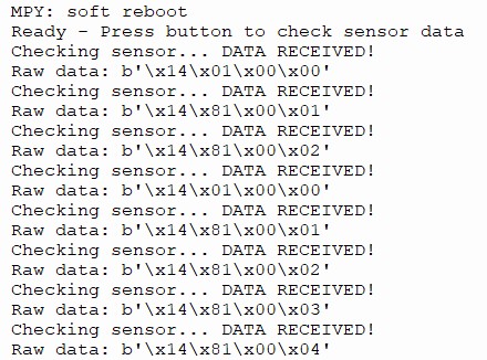
Video of the result
3.3 Arduino Version (C++)
For comparison, I also implemented the same functionality using the Arduino IDE. Since I was already comfortable with Arduino from previous projects, this was a familiar approach.
#include <Adafruit_BNO08x.h>     // Library for the sensor

#define BNO08X_I2C_ADDR 0x4A     // Address of the sensor

// Pin definition
const int buttonPin = D7;       // Button connected to D7
const int ledPin = D6;          // LED connected to D6

//Button state variables
int buttonState = 0;            // Button state (pressed = HIGH, released = LOW)
int lastButtonState = 0;        // Previous button state for edge detection

Adafruit_BNO08x bno08x;
sh2_SensorValue_t sensorValue;  // Structure to store sensor data

void setup() {
  // Initialize serial monitor for output data
  Serial.begin(115200);

  // Configure GPIO pins
  pinMode(ledPin, OUTPUT);     // LED pin as OUTPUT (lights up on button press)
  pinMode(buttonPin, INPUT);   // Button pin as input (read HIGH when pressed)

  // Initialize sensor
  bno08x.begin_I2C(BNO08X_I2C_ADDR);

  // Enable accelerometer data reporting
  // Sensor will now continuously provide acceleration data (X, Y, Z in m/s²)
  bno08x.enableReport(SH2_ACCELEROMETER);

  // Indicate that system is ready
  Serial.println("Ready - Press button");
}

void loop() {
  // Read current button state (HIGH = pressed, LOW = released)
  buttonState = digitalRead(buttonPin);

  // Check the button
  if (buttonState == HIGH) {

    // Turn LED ON to indicate button press
    digitalWrite(ledPin, HIGH);

    // Check if this is a NEW press (was LOW before)
    // This prevents multiple readings while holding the button
    if (lastButtonState == LOW) {

      // Try to get sensor data from BNO085
      if (bno08x.getSensorEvent(&sensorValue)) {

        // Check if received data is accelerometer reading
        if (sensorValue.sensorId == SH2_ACCELEROMETER) {
          // Print timestamp and X,Y,Z values
          Serial.print(millis());
          Serial.print(" ms: ");
          Serial.print(sensorValue.un.accelerometer.x, 2);
          Serial.print(", ");
          Serial.print(sensorValue.un.accelerometer.y, 2);
          Serial.print(", ");
          Serial.println(sensorValue.un.accelerometer.z, 2);
        }
      }
    }
  } else {
    // Button not pressed - turn LED OFF
    digitalWrite(ledPin, LOW);
  }

  // Save current button state for next loop iteration
  lastButtonState = buttonState;

  // Small delay to prevent overwhelming the system and provide basic debouncing
  delay(10);
}
Note on Arduino: In Arduino, hardware I2C works automatically on pins D4 (SDA) and D5 (SCL) because the Adafruit library uses the Wire library which initializes hardware I2C. This is why the Arduino code worked without needing SoftI2C.
Here is the ARDUINO result
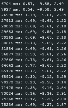
Video of the result
4. Testing and Results
Hardware Setup:
- 1x Seeed XIAO RP2040
- 1x BNO08x
- 1x Push button
- 1x LED
- Jumper wires
Wiring Diagram:
You can find how I connected wires on top of the page
BNO08X → XIAO RP2040
-------------------
VCC    → 3.3V
GND    → GND
SDA    → D4 (GPIO6)
SCL    → D5 (GPIO7)

Button → XIAO RP2040
-------------------
One leg → D7 (GPIO1) - resistor - GND
Other leg → 3v3

LED → XIAO RP2040
-------------------
Anode → D6 (GPIO0) through a resistor
Cathode → GND
Test Procedure:
- I2C Verification: First, I ran an I2C scan in MicroPython REPL to verify the BNO08x was detected at address 0x4A.
- Button Test: Pressed the button on D7 and observed the LED and Serial Monitor output.
- Comparison: Ran both MicroPython and Arduino versions to compare behavior and performance.
Observations:
| Test | MicroPython Result | Arduino Result |
|---|---|---|
| I2C Detection | Detected at 0x4A | Detected at 0x4A |
| Button Press | LED ON, prints raw data | LED ON, prints formatted data |
| Sensor Reading | Reads raw bytes (4 bytes) | Reads formatted accelerometer values (X,Y,Z) |
| Output Format | Raw hex data | Human-readable values with 2 decimal places |
| Response Time | ~50ms delay | ~5ms delay (faster) |
5. Comparison: MicroPython vs Arduino
Since I implemented the same functionality in both environments, I was able to directly compare their development workflows:
| Aspect | MicroPython (Thonny) | Arduino (C++) |
|---|---|---|
| Learning Curve | Gentle - Python-like syntax | Moderate - C++ syntax |
| Setup Time | Quick - flash firmware, connect | Quick - install board support |
| Compilation | No compilation (interpreted) | Compiled to binary (~5-10 sec) |
| REPL/Interactivity | Yes - test commands live | No - must upload to test |
| Code Length | ~40 lines | ~50 lines |
| Data Output | Raw bytes (requires parsing) | Formatted values (ready to use) |
| Performance | Slower (interpreted) | Faster (compiled) |
| Debugging | Print statements + REPL | Serial.print statements |
| Library Support | Good (machine, time) | Extensive (Adafruit libraries) |
| Memory Usage | Higher (VM overhead) | Lower (compiled binary) |
My Experience:
Having used Arduino extensively before, I found MicroPython refreshingly simple for this task. The ability to test I2C commands directly in the REPL was invaluable for verifying sensor connectivity before writing the full program. However, the Arduino version produced more useful output (actual accelerometer values vs raw bytes) and ran faster due to compilation.
For future projects, I would choose:
- MicroPython for prototyping, education, and when I need interactive debugging
- Arduino for production code, performance-critical applications, and when I need to leverage existing C++ libraries
6. Reflection
This assignment provided a comprehensive look into the embedded development lifecycle, from reading hardware manuals to implementing functional I2C communication with a sensor in two different programming environments.
Datasheet Deep-Dive: I learned that datasheets are essential for understanding not just pinouts, but also protocol requirements, addressing schemes, and configuration options.
MicroPython vs Arduino Experience:
- Since I was already comfortable with Arduino, switching to MicroPython felt like learning a new dialect. The REPL was a game-changer—I could test i2c.scan() and see the sensor appear immediately without compiling and uploading.
- The Arduino code produced cleaner output (actual float values) because the Adafruit library handled all the protocol parsing. In MicroPython, I only got raw bytes, which would require additional parsing to get meaningful values.
- This contrast highlighted the trade-off between control (MicroPython gives raw access) and convenience (Arduino libraries do the heavy lifting).
How AI Helped Me:
- ChatGPT helped me understand the SoftI2C vs hardware I2C issue by explaining the pin limitations of RP2040
- AI generated initial code structure, but I had to debug and fix it for my specific hardware
- AI suggested the
try-exceptblock for graceful error handling when sensor is not connected - The AI prompts I used are documented at the beginning of this assignment
System Integration: This project successfully demonstrated how to integrate:
- Input: Button press detection with debouncing
- Output: LED feedback synchronized with button state
- Communication: I2C protocol to read from a sensor and verify its presence
Future Improvements:
- Parse the raw I2C data in MicroPython to extract meaningful accelerometer values
- Add support for reading other sensor reports (gyroscope, magnetometer)
- Implement wireless transmission of sensor data via Bluetooth or WiFi
Overall, this project successfully demonstrated how to interact with input (button), output (LEDs), and wired communication (I2C with BNO085 sensor), while also giving me valuable experience comparing two different development workflows on the same hardware platform.