11. Input Devices
Group Assignment
This week, our group explored the fundamental differences between analog and digital signals, measured real sensor data using an oscilloscope, and analyzed I²C communication protocols.
You can read our full group documentation here: Group Assignment: Analog/Digital Signals & I²C Communication
What I Learned from the Group Assignment
| Topic | What I Learned |
|---|---|
| Analog vs Digital | Analog signals are continuous (sine waves) but sensitive to noise. Digital signals use discrete 0/1 values (square waves) and are more noise-resistant. |
| I²C Protocol | Uses two lines: SCL (clock) and SDA (data). The clock synchronizes communication between microcontroller and sensor. |
| Oscilloscope Usage | I learned to identify start/stop conditions on I²C and measure voltage levels of analog signals. |
| ADC Resolution | Analog readings (0-1023 for 10-bit ADC) need conversion to understand real-world values. |
These concepts directly helped me debug my BNO085 sensor connection. Understanding I²C timing on the oscilloscope confirmed that my SDA/SCL lines were working correctly before I even wrote any code.
Individual Assignment
Objective
This week, I connected and programmed a STEMMA QT BNO085 Accelerometer to read: - Accelerometer data (X, Y, Z axes in m/s²) - Gyroscope data (X, Y, Z axes in rad/s) - Rotation Vector (quaternion converted to Roll, Pitch, Yaw angles in degrees)
Hardware Setup
PCB Used
I used my custom PCB designed in Week 7: Electronics Design. You can see the PCB documentation here: Week 7 - Electronics Design (my PCB)
Sensor Connection
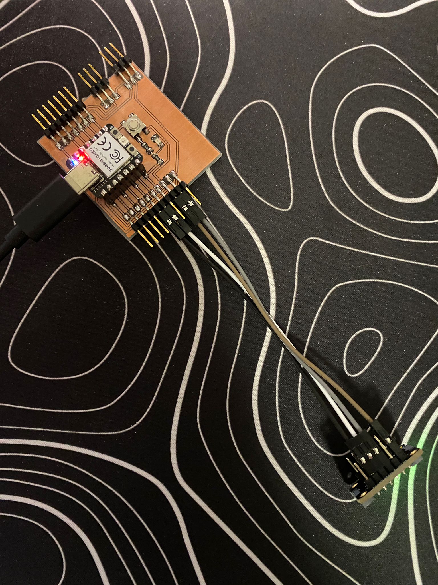
I connected the BNO085 to my PCB using the STEMMA QT connector. Based on my PCB design, I verified the following pins:
| BNO085 Pin | PCB Pin | Function |
|---|---|---|
| VIN | 3.3V | Power |
| GND | GND | Ground |
| SCL | SCL (GPIO5) | I²C Clock |
| SDA | SDA (GPIO4) | I²C Data |
Connection photo:
Sensor powered on (green LED indicates working):
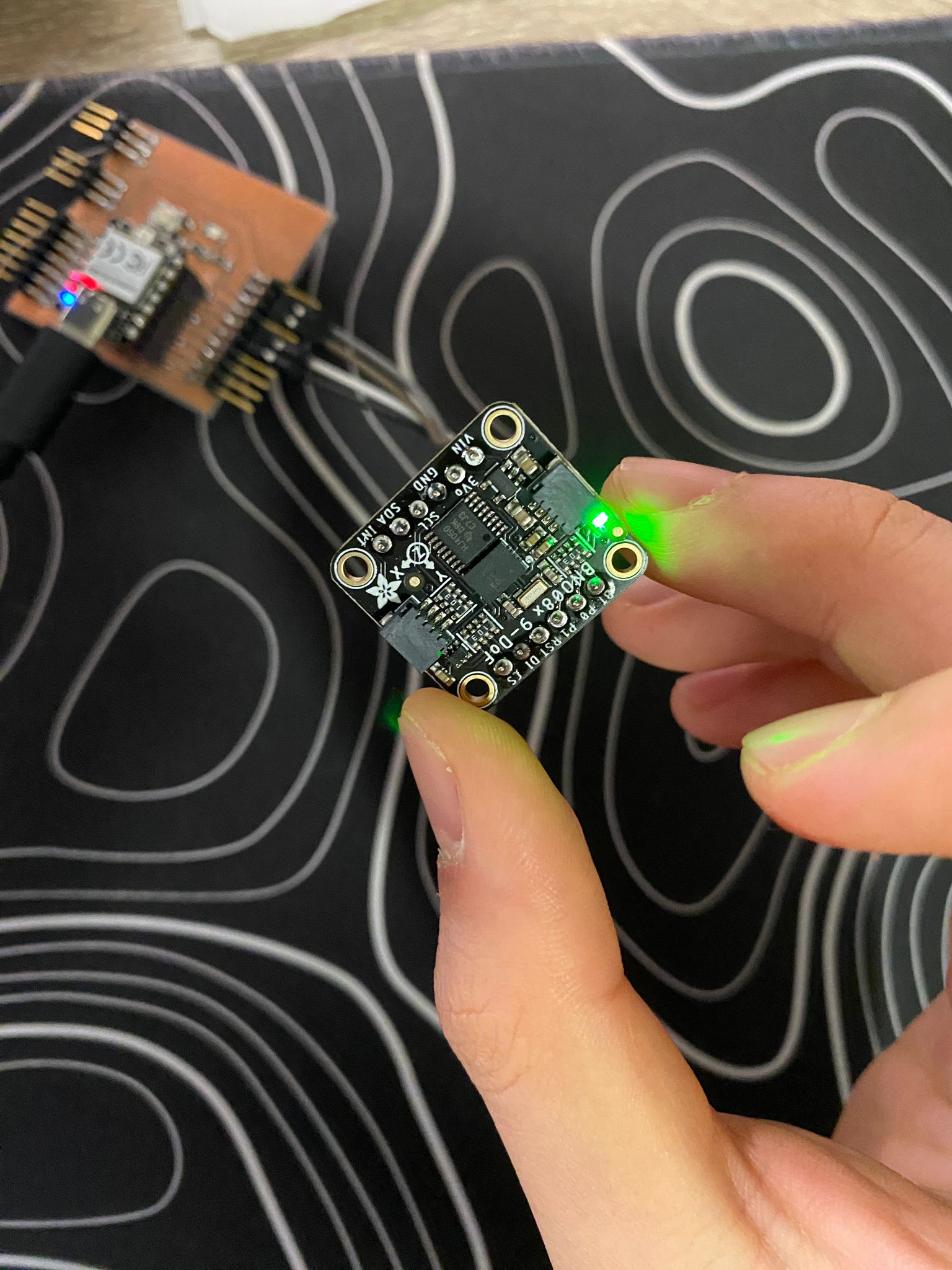
The green LED on the BNO085 confirmed that power and ground connections were correct.
Code Implementation
Source of Code
I did not write the code completely from scratch. I used:
| Source | Link | What I Used |
|---|---|---|
| Adafruit Library Examples | Adafruit BNO08x GitHub | Basic structure for reading accelerometer/gyroscope |
| Adafruit Learning Guide | BNO08x Guide | How to enable reports and use quaternion math |
| AI (ChatGPT) | Prompt: “Convert quaternion to Euler angles for BNO085” | The math conversion for Roll, Pitch, Yaw |
My Process
- First, I ran the example
bno08x_test.inofrom the Adafruit library to verify the sensor was detected. - Then, I modified the code to only enable Accelerometer and Gyroscope reports.
- Finally, I added the Rotation Vector report and the quaternion-to-Euler conversion using AI help.
AI Prompt Used
I am using Adafruit BNO085 with ESP32-C3. I have the rotation vector (real, i, j, k).
How do I convert this quaternion to Roll, Pitch, Yaw angles in degrees? Write the C++ code.
The AI gave me the atan2 and asin math formulas. I tested and verified them.
Part 1: Reading Accelerometer & Gyroscope
Code
#include <Adafruit_BNO08x.h>

#define BNO08X_I2C_ADDR 0x4A

Adafruit_BNO08x  bno08x;
sh2_SensorValue_t sensorValue;

void setup() {
  Serial.begin(115200);
  while (!Serial) delay(10);

  Serial.println("BNO08x Test - Accelerometer & Gyroscope");

  if (!bno08x.begin_I2C(BNO08X_I2C_ADDR)) {
    Serial.println("Failed to find BNO08x chip");
    while (1) { delay(10); }
  }

  Serial.println("BNO08x Found!");

  // Enable Accelerometer (500Hz)
  if (!bno08x.enableReport(SH2_ACCELEROMETER)) {
    Serial.println("Could not enable accelerometer");
  }

  // Enable Gyroscope (500Hz)
  if (!bno08x.enableReport(SH2_GYROSCOPE_CALIBRATED)) {
    Serial.println("Could not enable gyroscope");
  }
}

void loop() {
  if (bno08x.wasReset()) {
    Serial.println("Sensor was reset");
    bno08x.enableReport(SH2_ACCELEROMETER);
    bno08x.enableReport(SH2_GYROSCOPE_CALIBRATED);
  }

  if (!bno08x.getSensorEvent(&sensorValue)) {
    return;
  }

  switch (sensorValue.sensorId) {
    case SH2_ACCELEROMETER:
      Serial.print("Accel - X: "); Serial.print(sensorValue.un.accelerometer.x);
      Serial.print(" Y: "); Serial.print(sensorValue.un.accelerometer.y);
      Serial.print(" Z: "); Serial.println(sensorValue.un.accelerometer.z);
      break;

    case SH2_GYROSCOPE_CALIBRATED:
      Serial.print("Gyro  - X: "); Serial.print(sensorValue.un.gyroscope.x);
      Serial.print(" Y: "); Serial.print(sensorValue.un.gyroscope.y);
      Serial.print(" Z: "); Serial.println(sensorValue.un.gyroscope.z);
      break;
  }
  delay(100);
}
Output
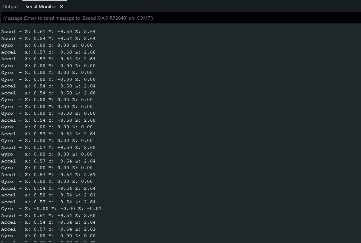
Interpretation: - Accelerometer values around 0, 0, 9.8 → Sensor is flat on table (gravity on Z-axis) - Gyroscope values near 0 → Sensor is not rotating
Part 2: Reading Rotation Vector (Roll, Pitch, Yaw)
Code
#include <Adafruit_BNO08x.h>
#include <math.h>  // For atan2, asin

#define BNO08X_I2C_ADDR 0x4A
Adafruit_BNO08x  bno08x;
sh2_SensorValue_t sensorValue;

void setup() {
  Serial.begin(115200);
  while (!Serial) delay(10);

  Serial.println("BNO08x - Rotation Vector (Roll, Pitch, Yaw)");

  if (!bno08x.begin_I2C(BNO08X_I2C_ADDR)) {
    Serial.println("Failed to find BNO08x chip");
    while (1) delay(10);
  }

  // Enable Rotation Vector report (100Hz)
  if (!bno08x.enableReport(SH2_ROTATION_VECTOR)) {
    Serial.println("Could not enable rotation vector");
  }
}

void loop() {
  if (bno08x.wasReset()) {
    bno08x.enableReport(SH2_ROTATION_VECTOR);
  }

  if (!bno08x.getSensorEvent(&sensorValue)) return;

  if (sensorValue.sensorId == SH2_ROTATION_VECTOR) {
    // Quaternion components
    float r = sensorValue.un.rotationVector.real;  // w
    float i = sensorValue.un.rotationVector.i;     // x
    float j = sensorValue.un.rotationVector.j;     // y
    float k = sensorValue.un.rotationVector.k;     // z

    // Convert Quaternion to Euler Angles (Radians)
    float roll_rad  = atan2(2.0 * (r * i + j * k), 1.0 - 2.0 * (i * i + j * j));
    float pitch_rad = asin(2.0 * (r * j - k * i));
    float yaw_rad   = atan2(2.0 * (r * k + i * j), 1.0 - 2.0 * (j * j + k * k));

    // Convert Radians to Degrees
    float roll_deg  = roll_rad  * 180.0 / PI;
    float pitch_deg = pitch_rad * 180.0 / PI;
    float yaw_deg   = yaw_rad   * 180.0 / PI;

    Serial.print("Roll: ");  Serial.print(roll_deg);
    Serial.print(" | Pitch: "); Serial.print(pitch_deg);
    Serial.print(" | Yaw: ");   Serial.println(yaw_deg);
  }
}
Output
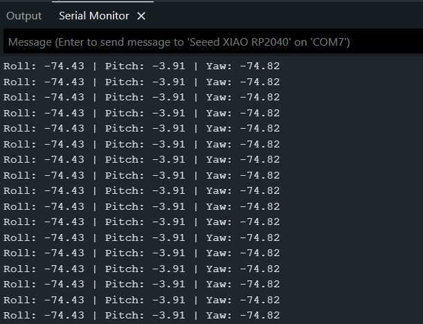
Angle Definitions:
| Angle | Meaning | Example |
|---|---|---|
| Roll | Tilting left or right (like airplane wings) | Positive = right wing down |
| Pitch | Tilting forward or backward (nose up/down) | Positive = front up |
| Yaw | Rotating left or right (compass heading) | Positive = turning right |
Testing Results
| Test | Action | Expected Result | Actual Result |
|---|---|---|---|
| 1 | Sensor flat on table | Accel Z = 9.8, Gyro = 0 | Passed |
| 2 | Tilt sensor left | Roll becomes negative | Passed |
| 3 | Tilt sensor forward | Pitch becomes negative | Passed |
| 4 | Rotate sensor clockwise | Yaw increases | Passed |
| 5 | I²C connection | Sensor detected at 0x4A | Passed |
Reflection
What I learned from combining Group + Individual work:
The group assignment taught me how to use an oscilloscope to verify I²C signals. When my BNO085 was not detected initially, I probed the SCL and SDA pins and saw clean clock and data pulses. This confirmed my wiring was correct, and the problem was in my code (wrong I2C address). Without this skill, I would have wasted hours re-checking wires.
What I learned from this individual assignment:
| Concept | What I Learned |
|---|---|
| I²C Addressing | BNO085 uses address 0x4A by default (PS0 pin to GND). I learned to scan for I2C devices when unsure. |
| Sensor Fusion | The rotation vector combines accelerometer, gyroscope, and magnetometer data into stable quaternion output. |
| Quaternion to Euler | Converting quaternion to Roll/Pitch/Yaw requires math (atan2, asin). I used AI to help with the formulas. |
| Data Rates | Different reports have different update rates. Accelerometer runs at 500Hz, rotation vector at 100Hz. |
Files
bno085_accel_gyro.ino: Reads Accelerometer + Gyroscope data
bno085_rotation_vector.ino: Reads Roll, Pitch, Yaw from rotation vector